Close
0%
0%

IKEA Vindriktning IAQ

IKEA Vindriktning + BME688 + SGP30 + WS2812 connected to an ESP8266 running Tasmota

Similar projects worth following
I had the feeling that the air in my living room wasn't very good but had no way to actually measure it. So I bought an IKEA Vindriktning since I didn't really know where to start and it is a quite cheap device.
Since IKEA devices are known to be quite hackable I did a bit of searching and sure enough there were quite a few mods already. So I decided to put together my own version with a few more sensors and some lights and share my experience of the process.

Obviously this is not the first modification of a Vindrktning (see #IKEA Vindriktning PCB and #IKEA Vindriktning Daughterboard) but I think I did some unique things that are worth sharing.
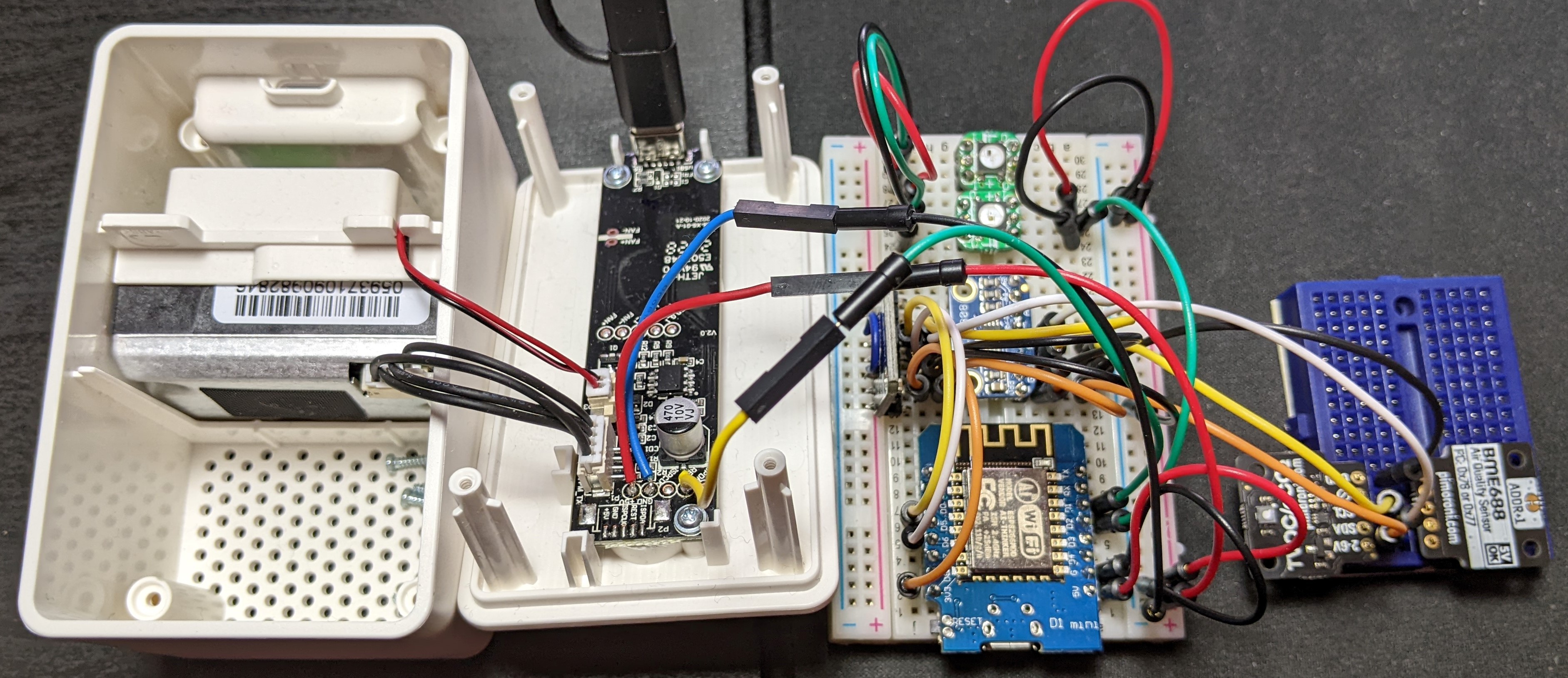
Development setup
Development setup with additinal CCS811 and MCP9808

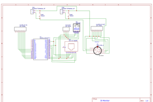
See the project log Inspirations/references for more resources and the files section for my Eagle PCB design.

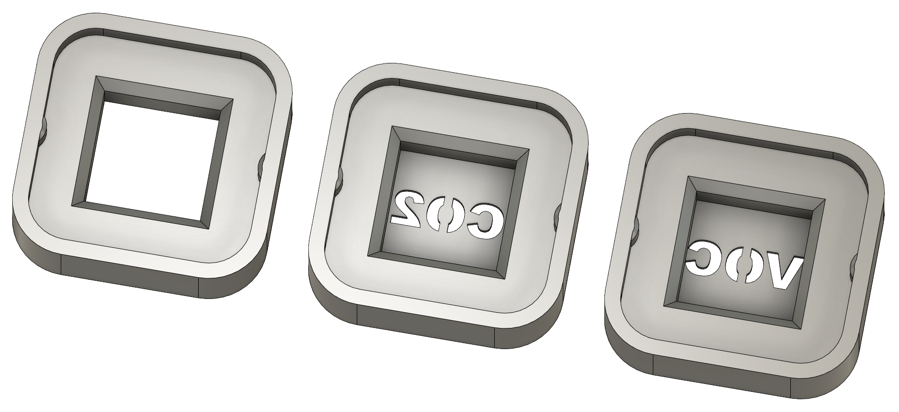
When starting the project I contemplated whether to just go quick and dirty and point-to-point wire everything and stuff it into the Vindriktning case or to go @lond's route and make it more polished. For just attaching the Vindriktnings PCB to an ESP8266 I would probably have point-to-point wired it but since I wanted to add sensors and LEDs the wiring would get too elaborate and a PCB would be the way to go, so might as well make everything a bit more polished. Meaning custom PCB, neat wiring, connectors, 3D printed LED mounts and LEDs for the additional sensors to mirror the Vindriktnings LEDs for displaying PM2.5 levels.

I started with a CCS811 and MCP9808 and then added a BME688 and SGP30 to be used in the final implementation.

Read more »

ESP_IAQ_baseBoard_gerber.zip

PCB Gerber files

x-zip-compressed - 97.13 kB - 12/28/2022 at 15:32

Download

IKEA_Vindriktning_IAQ.zip

PCB schematics and EAGLE brd file

x-zip-compressed - 178.92 kB - 07/01/2022 at 08:24

Download

View all 18 components

View all 3 project logs

  • 1
    Assemble base PCB with ESP-12, connectors, etc.
  • 2
    Flash the ESP-12 firmware
    1. Bridge the solder jumper on the back of the base PCB according to your serial adaptors voltage.
    2. Connect serial adaptor. The staggered holes in the PCB should allow you to just plug in a cable without the need to solder headers
    3. Flash firmware (Tasmota, ") using desired tool (Tasmotizer)
    4. Remove solder bridge if it is too big to insert the base PCB into the Vindriktning case
  • 3
    Solder 5-pin connector to Vindriktning PCB

View all 12 instructions

Enjoy this project?

Share

Discussions

Similar Projects

Does this project spark your interest?

Become a member to follow this project and never miss any updates