Indicator panels are intended for displaying various information. Whether the current value of the register (16-bit input exactly for this), or something else received by UART. Anyway, you can always make a clock :). Why are the 6 not 8? Just because 100x100mm PCB very cheap.

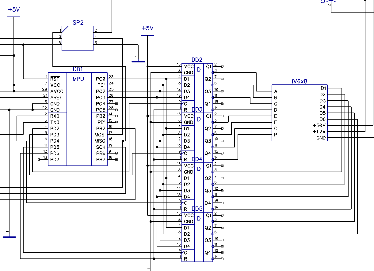
Circuitry is simple and was done on the principle "From what I found." And I found a pinch of ATMega168 controllers and two hundred cases of quad D-flip-flops K155TM8

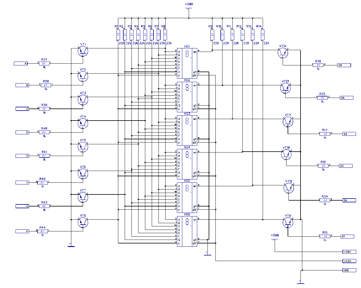
Segments
in parallel, everything is polled up to power and shunted to ground by
transistors. Keys, by the way - 2N2222 - at 60V.

It's clear that besides the board itself, you need a firmware too, so we uncover AVR ISP mkII, Atmel Studio and remember what it is - debug the programs having only some digital outputs available.
The firmware is here: https://github.com/radiolok/brainfuckpc/tree/master/fw

The ASCII table is clogged with dashes. Only HEX-numbers have been added so far. Does anyone have a more complete table? To be honest, I have not looked for it yet, but I'm too lazy to fill in the letters myself. Formatting tabs, yeah, where without it ...
Happiness? No. After sending ABCDEF I got EBFACD.
Crap - digits are not in order to simplify wiring. Dirty hack in the form of an array of six elements solves the problem. So what? The code will all endure.
Working!
The refresh rate is 500Hz, this is more than enough to not see the flicker alive.
Next tasks: add a UART-ring for messaging, find a bootloader for 8MHz, connect a 16-bit input.
 Artem Kashkanov
Discussions
Become a Hackaday.io Member
Create an account to leave a comment. Already have an account? Log In.