 Ultimate Robotics
The absence of logs here does not mean the absence of work on the project! It's time to synchronize current events.
As you learned from the "details" section, the first uMyo prototype turned out to be quite controversial.
From the positive points:
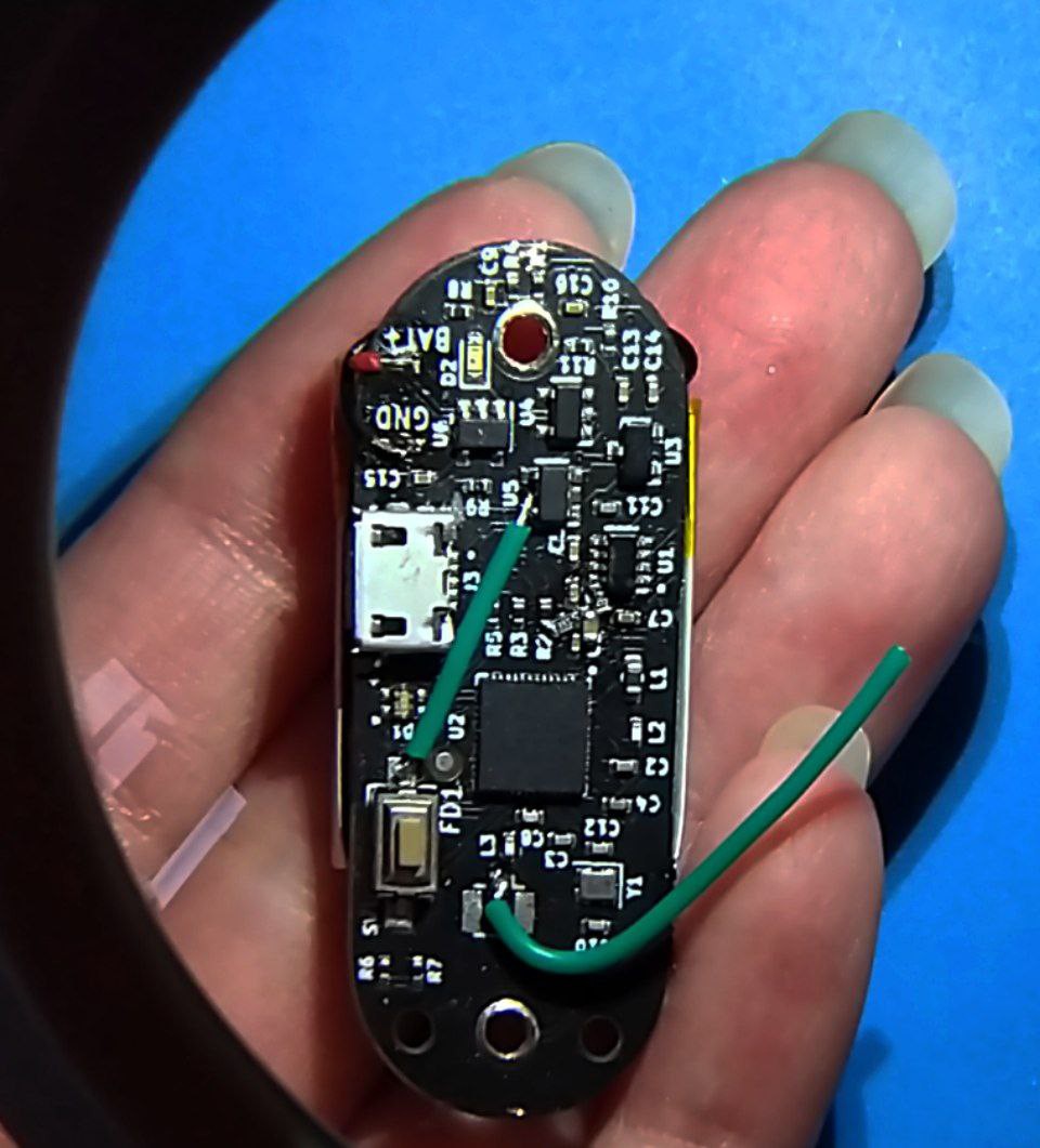
- the printed circuit board turned out to be quite small (46x18 mm)
- after a little debugging, we were able to work on the firmware
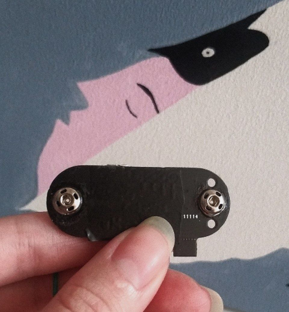
- by testing dry connectors (which we originally planned), we were able to expand the ways to receive an EMG signal
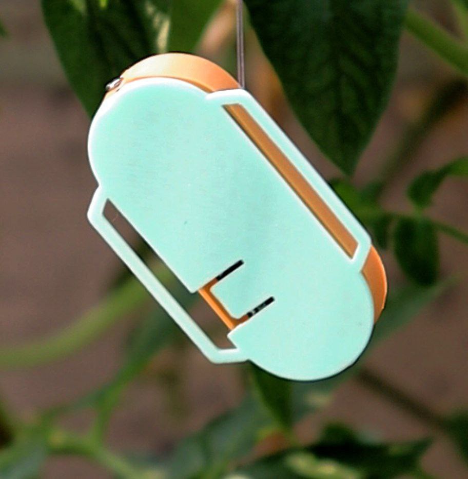
- we even printed the case to make it easier to attach to hand
Of the not-so-positive ones:
- although the debug was successful, the fix was hard to make - It was necessary to solder three SMD components with no pads for them, all in one place...
- as the optimal connectors were chosen, it became clear that the hole for the connectors needed to be expanded, which required changing the location of some tracks and components
- we printed a case for uMyo, but the idea was to create the simplest EMG sensor in the hardware part and give more functionality in the firmware part. Therefore, we had to think about how to implement the uMyo attachment to the hand using only a printed circuit board...
So that's what we did in May.
Next, you will learn how we solved the problems of connectors, board design, mounting methods, and also learn more about the functionality.
Discussions
Become a Hackaday.io Member
Create an account to leave a comment. Already have an account? Log In.