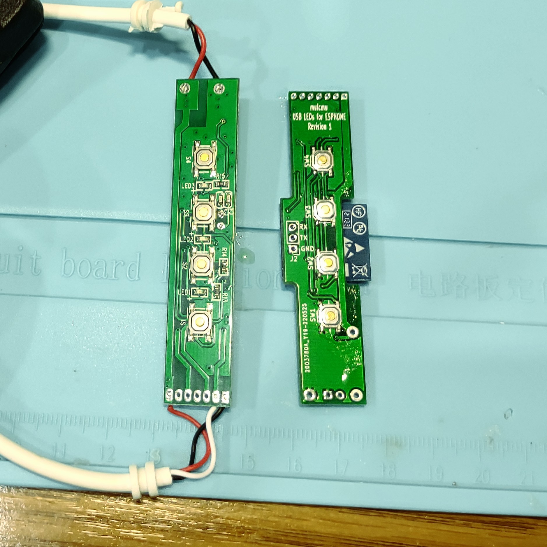
Revision 1 PCB was designed to fit inside the existing control enclosure for the lights. The ESP-WROOM would fit in the enclosure but needed some offset cuts in the PCB. A similar set of lights had the same controls but the plastic molding was different to retain the board in place. The PCB should fit either of these two style cases.
Ordered 5 prototype PCB from jlcpcb and stencil from oshstencil. The assembly went okay despite the solder paste going on a bit messy.
Initial testing went okay. The board kept resetting due to lack of pull-up on the reset line. The voltage supervisor was removed during the troubleshooting. Rev 2 in progress to add the pull-up resistor. Might change the supervisor to 3.3V too.
Arduino test code loaded on okay to test the lights and buttons. Took a good bit of searching to find the INPUT_PULLDOWN_16 to enable the pulldown on GPIO16.
Next step to get rev 2 PCB on order and start working on ESPHome configuration to properly IOT it into home assistant.

 mulcmu
Discussions
Become a Hackaday.io Member
Create an account to leave a comment. Already have an account? Log In.