Close
0%
0%

Street-racing silencer

Silence those annoying noisy street-racers with a push of a button

Public Chat
Similar projects worth following
This project is probably as illegal as the street-racing itself.

Ever since I have moved to a new apartment I am having trouble sleeping EVERY spring+summer. Why spring+summer? - because during this period, those pesky motorcycle and pimp-my-ride drivers are testing their skills on a nearby road. The speed limit is 50km/h but it does not stop them from driving at 150km/h after the midnight. This produces a lot of loud noises and reduces quality of life for everyone who lives here.

What do you think, is it possible to silence them by a press of a button from the comfort of my bed? - Hold my... sleeping pills.

What is it? - It is a "deploy and forget" device, solar powered, hacked with mostly re-used components from previous projects and other donor devices. Basically it is a *special* LED blinker.

There are three modes of operation:
- simulate police car lights
- simulate speed radar flash
- sleep mode

The RF transmission is *protected* by none other than KeeLoq.

This project consists of two parts:
  • The device, deployed remotely
  • The controller, at home

The nature of the project is most probably short-lived. That is because once it is revealed to the "general public" it will simply be ignored by those for whome it is designed to scare.

It would be just like telling the crows that a scare-crow is nothing to worry about.

This all means that a smart usage of this device is paramount if I want it to last.

For the controller part I have chosen to use Raspberry Pi, because I don't have the time/energy to build a nRF24L01 key-fob (which would be ideal for this project) and because I have a pi-hat from my previous project that I can re-use for this purpose.

Be sure to read Project Logs for all the details.

  • 1 × Solar panel 6V/1W
  • 1 × SB6284 Step up converter
  • 1 × LTC4054 Power Management ICs / Power Supply Support
  • 1 × MAX8888 Power Management ICs / Linear Voltage Regulators and LDOs
  • 1 × ATmega328P Microprocessors, Microcontrollers, DSPs / ARM, RISC-Based Microcontrollers

View all 14 components

  • Source of components

    trax06/30/2022 at 10:30 0 comments

    Just a little note on where I sourced some of the components:

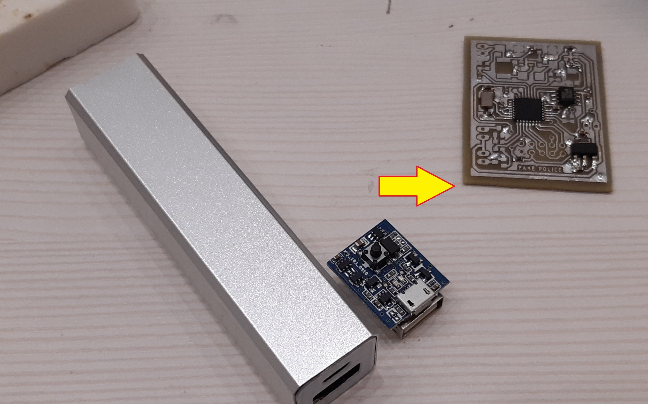
    Yes, it is the cheap-o USB travel charger.

    This little thing had many good parts required for this project:

    • Step up converter
    • Li+ charger IC
    • MOSFETs
    • Li+ Battery

    It also has a battery protection IC but I decided not to use it in this project.

    The step-up converter used in travel charger is responsible of providing 5V out of Li+ battery which can be anywhere from 3.7V to 4.2V.

    However, in my project, I actually step up the solar panel voltage to 5V and power the Li+ charger IC from it, which in turn charges the battery. Then the battery is being used through a MAX8888 LDO to power the ATmega328P and nRF24L01+ module.

    The 1W LEDs are directly connected to the battery and switched on via N channel MOSFETs.

  • Range issues and fixups

    trax06/30/2022 at 10:21 0 comments

    Yesterday I tested the range of nRF24L01+ modules used in the device and I was not happy. It was simply not working as reliable as it must so I made a little change.

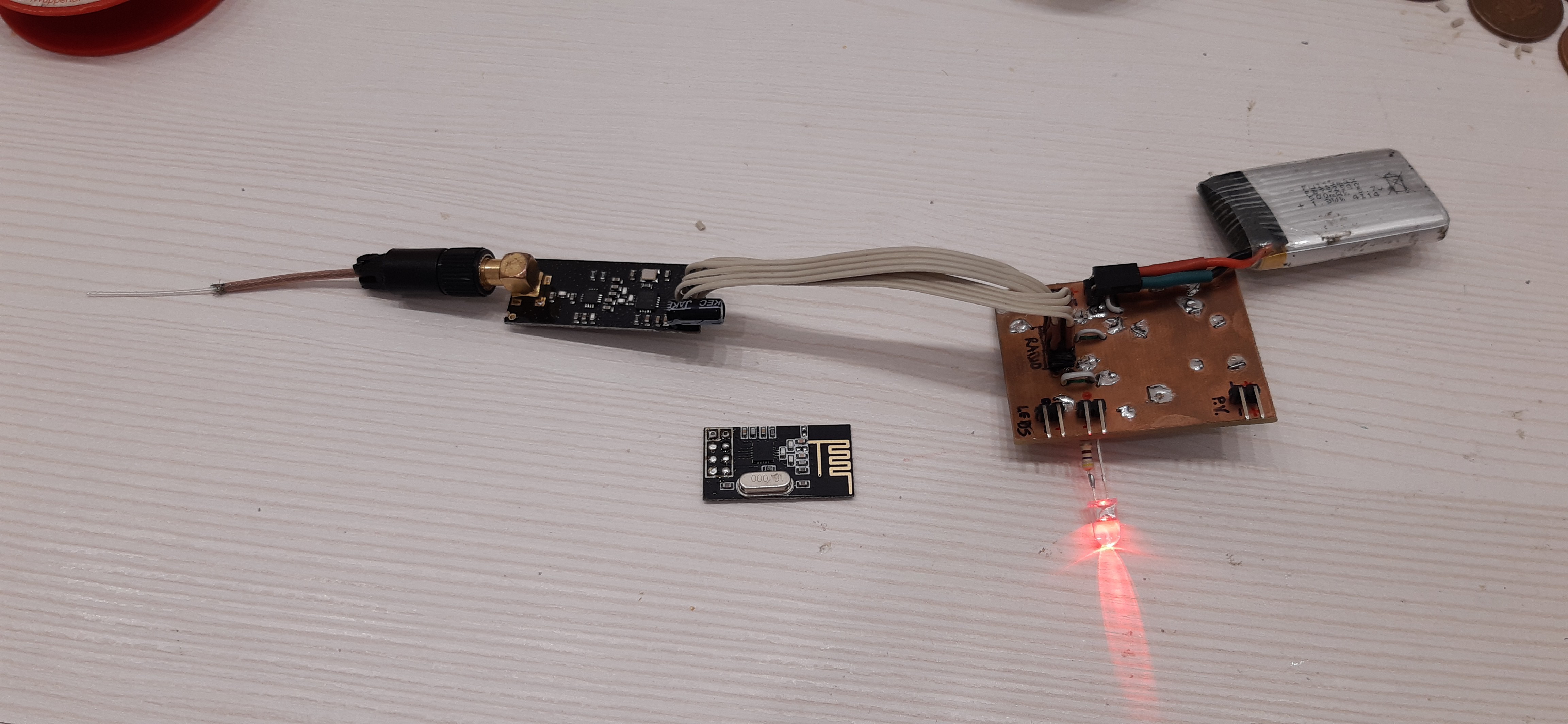
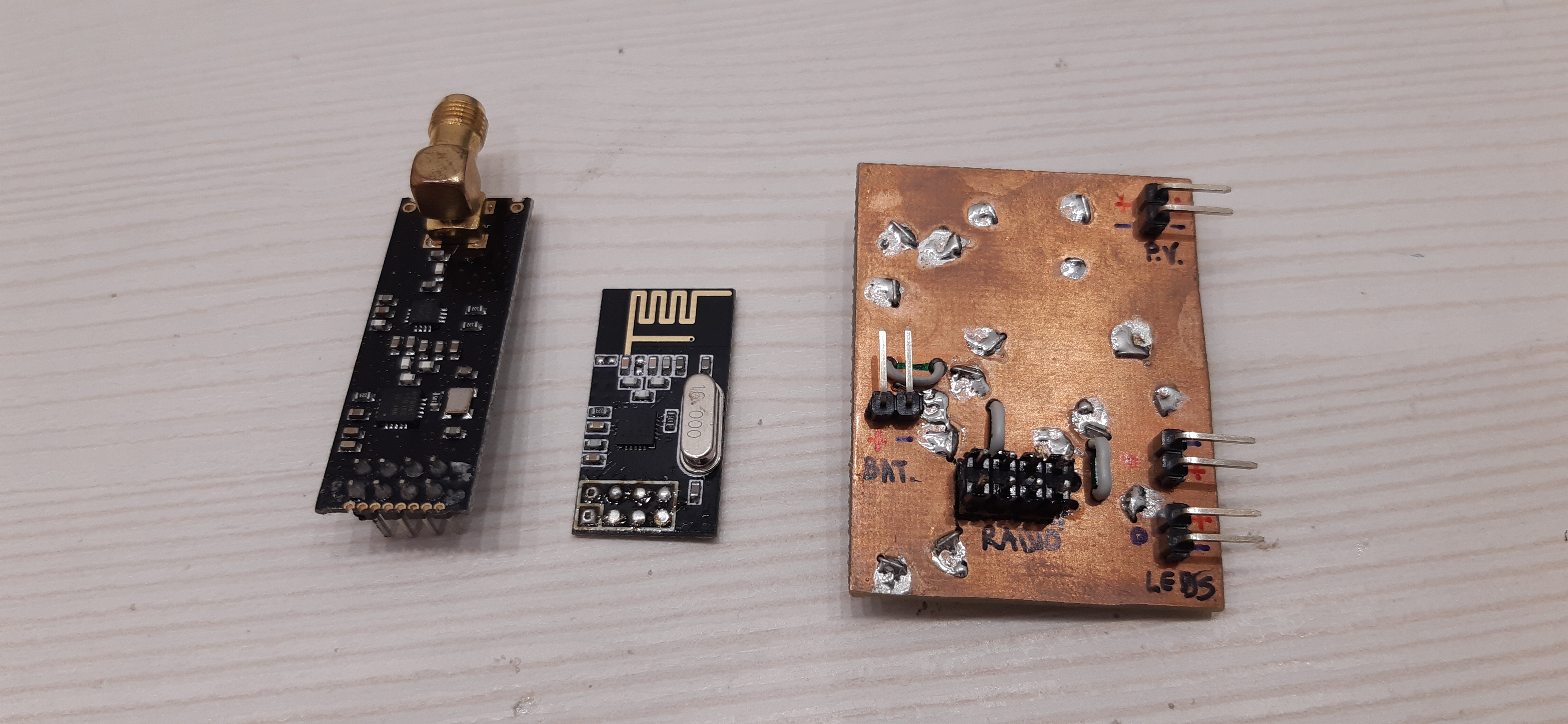
    I had to switch to the version with PA+LNA (which I luckily had at hand). These work much better and hopefuly it will not drain the battery too much during RX/TX.

    It had to be connected with wires because this version is much "longer" and there is simply no space in the current enclosure.

    It works!

  • LEDs mounted and casing change

    trax06/29/2022 at 13:14 0 comments

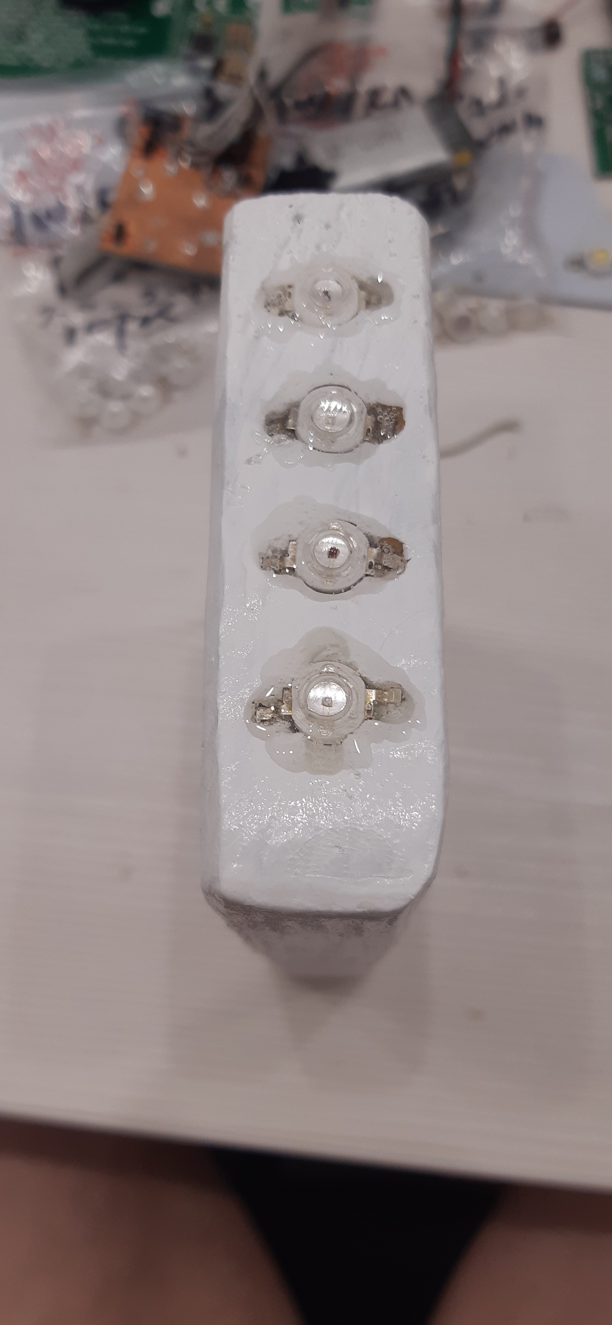
    LEDs have been mounted and covered with epoxine.

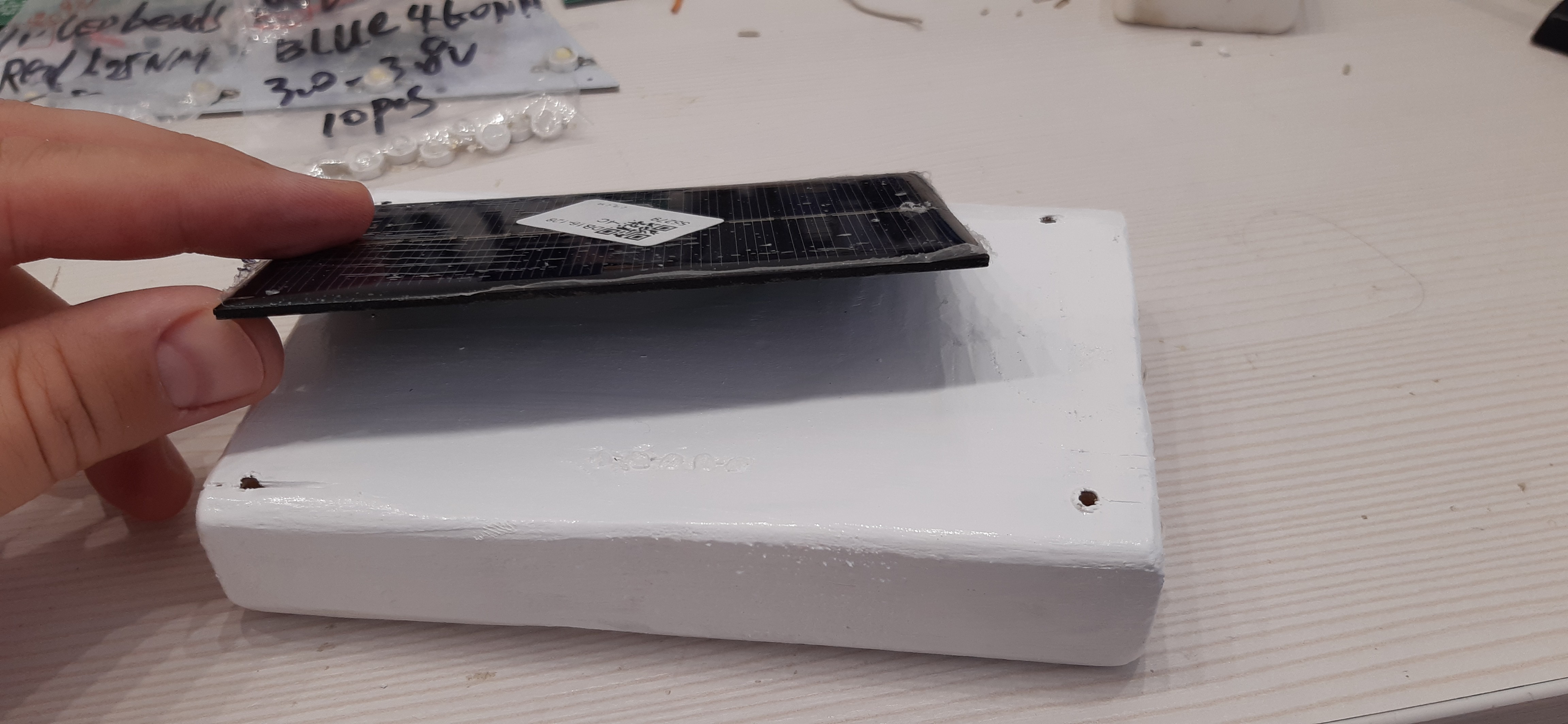
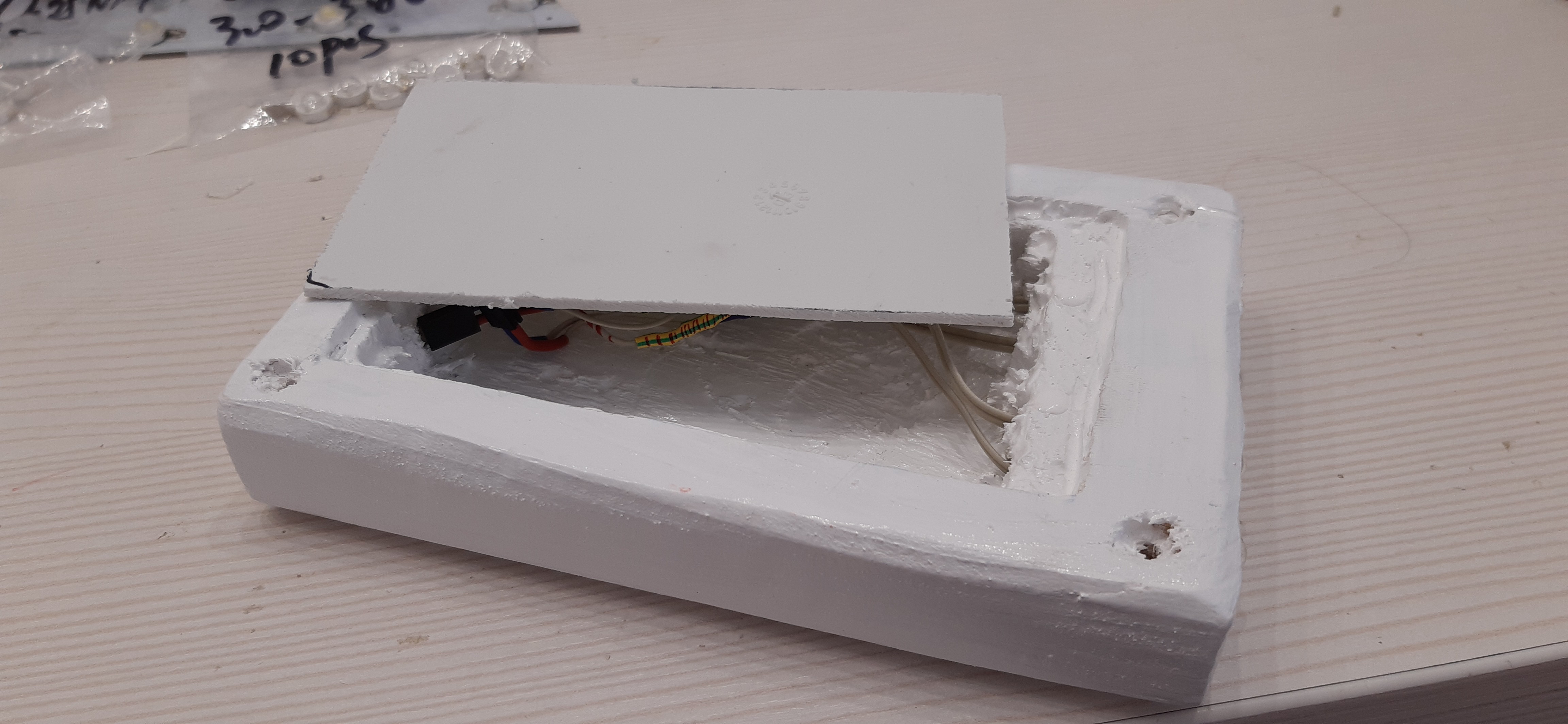
    Solar panel will be mounted on the other side, and the "slot" will be covered with a plastic cover. This is just to protect everything from the rain, since it is better to have the big opening facing down.

    A very small hole will be drilled for wires coming out of solar panel (under it) and everything will be siliconed.

  • Looking alive (debugging)

    trax06/27/2022 at 11:21 0 comments

  • More motivation

    trax06/27/2022 at 10:43 0 comments

    The summer is once again almost here. Roads are dry and straight. Crap.

    Last night it was impossible to fall a sleep until 00:30 because some idiot was riding a racing motorcycle at 200km/h in front of my building. Mind you, it is a great opportunity to do it because the road is straight and nobody is around. However, the mega loud noise it produces is the issue I am trying to resolve with this project.

    I have given up on calling the police, because it does not make sense to call them every week. They simply don't give a crap... maybe I should join the police or buy a motorcycle? Both of these would solve my problem.

    In the meantime, looking like a zombie is my new image.

  • The Controller (aka Remote)

    trax06/27/2022 at 10:26 0 comments

    I mentioned elsewhere that I will be using the Raspberry Pi in order to remotely control the device. I have a "pi hat" I designed for my previous project (it has a MAX485, a cooling fan and nRF24L01 receptable/pinheader). Of all this I will be using only the nRF24L01. I may even put the one with Power Amplifier on the Raspberry Pi.

    Software for the Raspberry is written in Python and it currently contains only the test code. You can check it out in the Github repository.

    I am using LeeKoq library (for the KeeLoq) and NRF24 library for the nRF24L01. The main entry point is the rftest.py script.

    When started, it loads the tx_counter.txt file which is used to keep track with the receiver (actually it is the other way around) and is incremented after each successful transmission. nRF24L01 has a confirmation for packet reception so I use that feature in order to not increase the synchronization counter more than required.

    Note: The current rftest.py does not verify the authenticity of received transmissions from the device. This will be implemented in the real program/script.

  • Battery consumption optimization

    trax06/27/2022 at 08:45 0 comments

    Even though I implemented everything in such a way so that ATmega328P is sleeping whenever it is not doing anything special, I forgot to put nRF24L01 to sleep as well. This resulted in constant current consumption of ~17mA which drained the battery from 4.2V to 4.0V over night.

    The original idea was to wake-up the ATmega328P whenever nRF24L01 receives a valid packet via it's IRQ pin but this needed more work.

    Now I implemented a mechanism where the device is in sleep mode, including the nRF24L01 for a predefined time-slot (4 seconds) after which the nRF24L01 is set to RX mode (listening for RF packet) for 1 second. In case it doesn't receive anything within that 1 second it goes back to sleep for next 4 seconds and so on. During that 1 second listening time, ATmega328P is actually sleeping - it will be woken up by the IRQ in case something is received.

    This all means that the device is unavailable for 4 seconds maximum, which is just fine.

    After the device is "woken up" it will remain in constant listening mode for 2 minutes. On every received valid command this time is reloaded for next 2 minutes. In case nothing is received it will go back to usual sleep mode (4 seconds sleep / 1 second listen).

  • Last minute hardware changes

    trax06/27/2022 at 08:38 0 comments

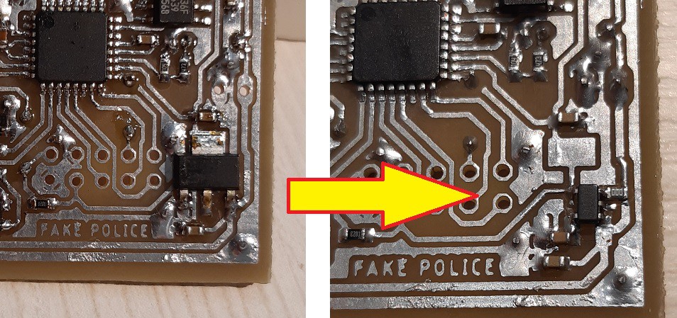
    LDO change

    Since this thing is powered by a Li+ battery (4.2V max) I needed to drop it to 3.3V for nRF24L01. This means using either some sort of buck converted or an LDO. Buck converter would be an overkill since voltage difference is not that great, neither are the currents, so I opted for the LDO AMS1117-3.3V. This was actually a bad idea since the voltage drop is too big, and I couldn't get more than 3.1V at the output. This meant some last-minute changes and LDO replacement, so I went for the MAX8888 LDO which is excellent for this application.

    Now I have a good 3.3V for entire usable range of battery voltage.

    Crystal change

    The idea was to use the external clock for ATmega328P but later on I found that I should better use the crystal clock inputs to Asynchroniously clock the internal Timer and implement an RTC. I removed the 8MHz crystal and soldered on the 32.768 kHz one and configured ATmega to use internal 8MHz clock. Now I have a somewhat accurate RTC (but not really because of the temperature drift). The RTC can be set remotely via the controller. Now I only need to figure out what to use it for instead of simply counting seconds and minutes for periodic operations (e.g. telemetry event).

  • Telemetry data

    trax06/27/2022 at 08:26 0 comments

    Since the device will be deployed outside, battery powered and re-charged via solar panel I thought it would be a nice idea to have it send me some periodic (or upon request) telemetry data. This includes:

    • Voltage of the solar panel
    • Voltage of the step-up converter afer the solar panel
    • Current battery voltage
    • Battery charge indicator (charging/not-charging)
    • Ambient temperature
    • Battery charge time (since last report)
    • Number of received RF commands but with a failed MAC (KeeLoq hacking attempt)

    The telemetry data sent by the device to the controller is also protected with a MAC so that I can verify it is the device sending me this data, not someone else.

  • KeeLoq on 2.4 GHz

    trax06/27/2022 at 08:16 0 comments

    After the device is deployed on the field, I need to make sure it is not misused by others eavesdropping on nRF24L01 packets. I wouldn't want someone else triggering the LEDs thus revealing the location of the device more than necessary.

    I could have used AES encryption to build a MAC (message authentication code) to verify authenticity of the transmission and also use a synchronization counter for re-transmission protection, but since this whole project is about re-using old parts I thought why not use old code as well.

    In one of my previous projects I worked with KeeLoq so I decided to re-use it to ensure some sort of protection against device takeovers. KeeLoq algorithm is known and is more-less crackable, however with secret 8 bytes-long encryption key it is still not feasible that someone will attempt to attack this little device. For those who succeed - they can take it away as a gift.

    The secrecy of transmission is not important in this device so KeeLoq is used only to prevent replay attack and for the authentication of the controller (me).

    Data which is prepared/encrypted with KeeLoq is transferred over nRF24L01 and it's 32-bytes long packets. KeeLoq ciphertext is only 4 bytes long and is used as a MAC (as a rolling code), while remaining of the payload is some other "application specific data".

    The "application data" transferred between the controller and the device also supports key-change, meaning I can change the KeeLoq "crypt key" any time I like after the device is deployed.

View all 11 project logs

Enjoy this project?

Share

Discussions

Similar Projects

Does this project spark your interest?

Become a member to follow this project and never miss any updates