 Sergio Ghirardelli
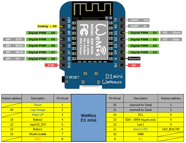
To build my wireless sensor network, I chose the Wemos mini board, based on the ESP8266 chip, for the following features:
• Compact dimensions
• Low price (around 6 euros)
• Possibility of being programmed with Arduino IDE
• Very low consumption: 70 mA with active wifi, 250 uA in deep sleep mode
• Built-in WiFi
• Possibility of using the ESP-NOW protocol
• Possibility of connecting I2C and Onewire sensors, through libraries available on the network
Project sizing and I / O list.
In order to confirm the choice, I made a preliminary study to understand if the Wemos mini was adequate for my needs.
Test bench.
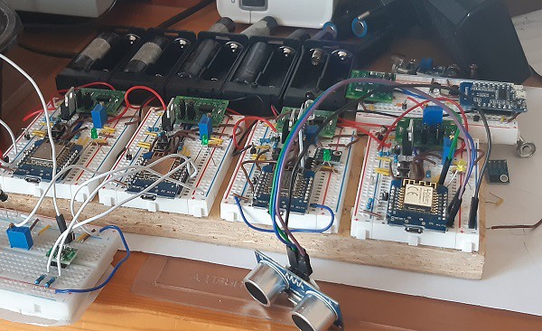
The next step was to build a portable test bench consisting of:
- n.4 breadboards in each of which I simulated the single sensor module, installing the wemos mini controller with the various buttons, LEDs and sensors added during the evolution of the project
- n.1 breadboard where I simulated the gateway module
On this test bench I developed all the hardware and software part of the project.
PCB design and construction
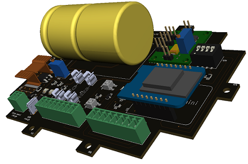
When I finished testing all the functions, I designed and built the PCB.
I chose to make the Wemos mini card removable, to simplify installation and possible replacement in case of failure.
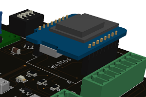
Switching to Wemos mini PRO
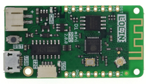
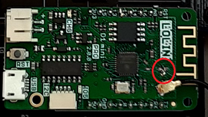
For the final product, i chose the PRO version, which allows the use of an external antenna, essential for reaching the minimum distance of 100 meters between one sensor module and the next.
In order to use the external antenna, it is necessary to move the position of the resistance from 0 ohm as in the figure below.
Discussions
Become a Hackaday.io Member
Create an account to leave a comment. Already have an account? Log In.