The display buffer is organized such that each byte corresponds to an 8 bit line of pixels going down. The display is 128x64 pixels. that means there are 128x8 bytes resulting in 1024 byte buffer. 8 bytes code for a 8x8 bit tile.
The following image describes how a tile is coded (Don't judge I'm not a pixel artist):
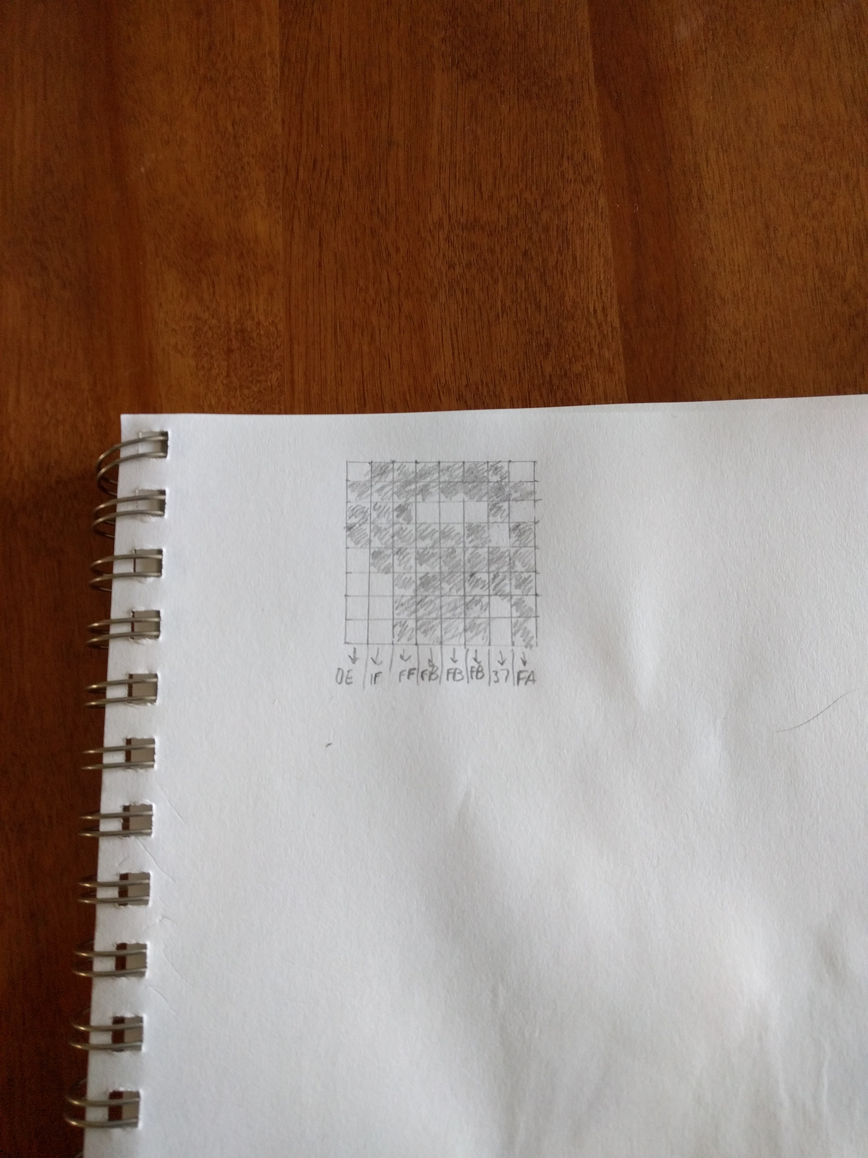
This translates to the following in assembly:
player_sprite:	.db 0x0e,0x1f,0xff,0xfb, 0xfb, 0xfb, 0x37, 0xfa
player_pos:		.db 4, 4
The following is the assembly code to copy this tile to the display buffer:
draw_player:
	ldi		yl, low(buffer)
	ldi		yh, high(buffer)
	movw	x, y
	ldi		zl, low(2*player_pos)
	ldi		zh, high(2*player_pos)
	lpm		r16, z+
	lpm		r17, z
	ldi		zl, low(2*player_sprite)
	ldi		zh, high(2*player_sprite)
	lpm		r19, z+
	ldi		r18, 8
	ldi		r21, 0

buf_pos_y:
	dec		r17
	breq	y_set
	rcall	next_line
	rjmp	buf_pos_y
y_set:
	mul		r16,r18
	add		xl, r0
	adc		xh, r1
	movw	y,x
	rcall	draw_tile
	ret
;;;;;;;;;;;;;;;;;;;;;;;;;;
draw_tile:
	ldi		r20, 8
fill_tile:
	st		y+, r19
	lpm		r19, z+
	dec		r20
	brne	fill_tile
end_draw:
	ret
;;;;;;;;;;;;;;;;;;;;;;;;;
next_line:
	adiw	x, 60	; increase buffer address by 128, new line
	adiw	x, 60
	adiw	x, 8
	ret
To increase the line curser I have to add 128. I couldn't find a command to add 128 so I used the adiw (which allows to add a max value of 63 to a 16 bit register).
To send the display buffer, the adafruit display() command was converted to assembly:
display:
	mcommand 0x21
	mcommand 0x00
	mcommand 127
	mcommand 0x22
	mcommand 0x0
	mcommand 0x7

	sbi PORTB, 2 ;cs high
	sbi PORTB, 1 ;dc low
	cbi PORTB, 2 ;cs high

	ldi r23,4
	ldi r22,0
	ldi r21,0
	ldi YL, low(buffer)
	ldi YH, high(buffer)

	send_buffer:
	ld r20, Y+
	rcall spi_send
	inc r21
	brne send_buffer
	inc r22
	cpse r22,r23
	brne send_buffer

	sbi PORTB, 2 ;cs

	ret
My way of counting to 1024 which is hex 0x400 is to use two registers r21 and r22. When (r22 ==4) I know I sent 1024 bytes.
Discussions
Become a Hackaday.io Member
Create an account to leave a comment. Already have an account? Log In.