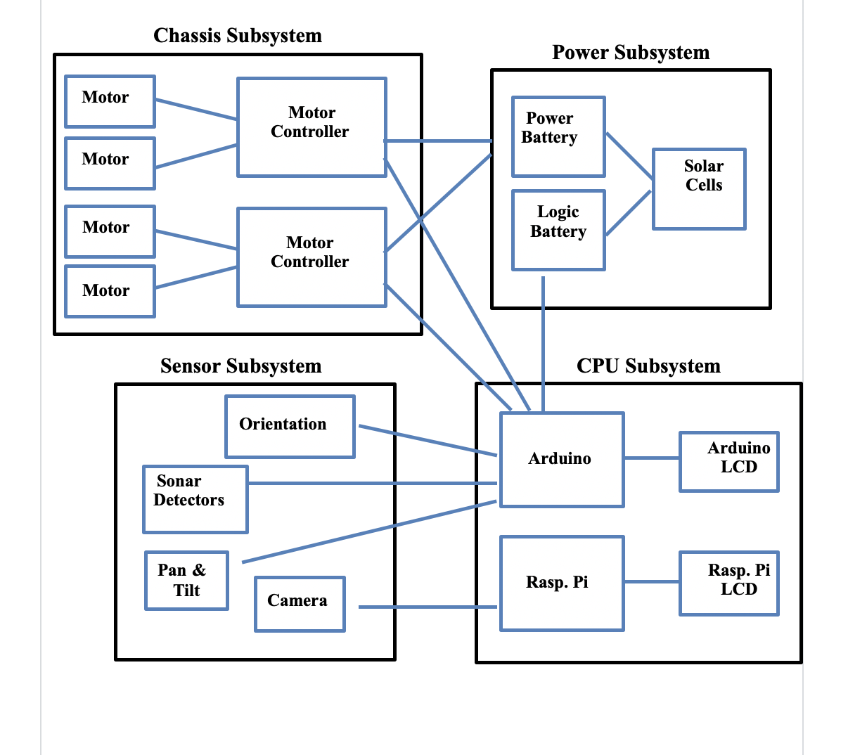
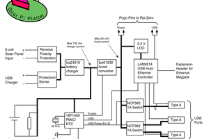
The diagram below shows the subsystems and their major physical components. Connecting each physical component is an interface line that has to be physically connected and possibly addressed from a software perspective.
Chasis Sub-System:
After decades of thought about how to build a chassis, with many failed attempts using both wood and plexiglass, I have decided to purchase a chassis. There are two basic types; tracked and wheeled. There are many advantages with tracked vehicles however all Mars rovers are wheeled. All the Mars rovers utilize a design concept called rocker bogie suspension. There are no suitable off the shelf rocker bogie chassis available. There are however 4-wheel drive chassis. The selected chassis is the one that I selected back in 2005.
The number and size of components dictates the size of the rover central box and therefore the size of the rover. The rover of choice is the Nomad robot chassis available from servocity.com. The interior cavity or central box is 8” x 3.68” x 2.64” high. The overall size is 15.9” x 14” x 8” high. The chassis weighs 6.45 pounds and has a max speed of 5 MPH at 12 volts. The tires are 5.4” in diameter, perfect for uneven terrain. There are plenty of external mount points for sensors. The kit is made from components that remind me of the Erector Set of old.
1. Locomotion
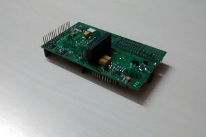
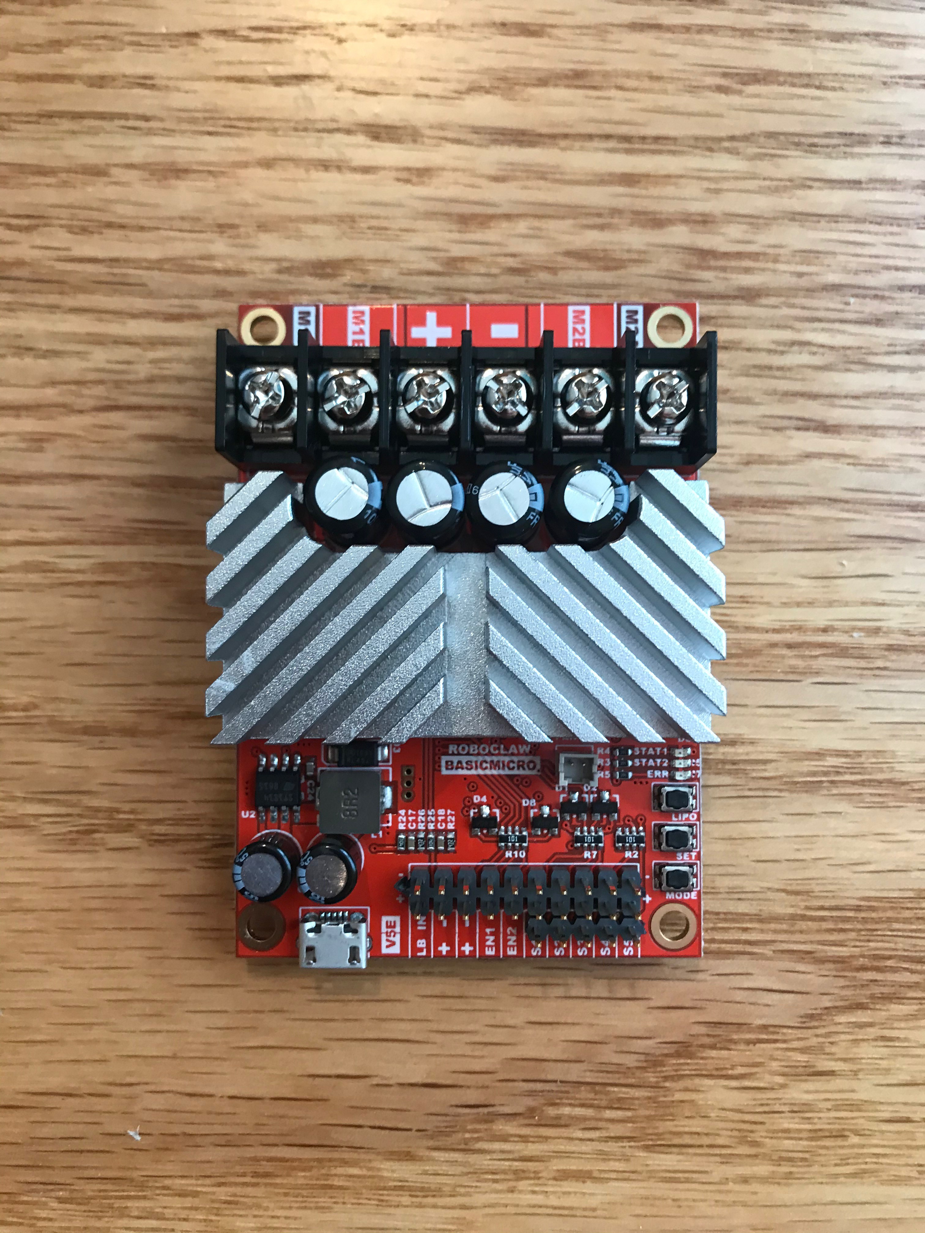
Four motors are provided by the chassis kit. They are DC motors and they need motor controllers. The controllers of choice are Roboclaw motor controllers. Each board controls two motors. This requires two controller boards. These boards are very sophisticated.
The motors provided are 313 RPM heavy duty planetary gear motors that can propel the rover up to 5 MPH. They require a minimum of 6 volts with a maximum of 12 volts. The no load current is 0.52A and their stall current is 20A.
Given the stall amps, the proper size for the controller boards is the 2x15A boards which can handle a continuous draw of 15A and a surge of 30A. The size of these boards is 2.92” x 2.05” x 0.67” high. The Roboclaw setup software runs on Windows only. The manuals can be found at www.basicmicro.com.
The wires going to the motors need to be as short as possible. Given this and the fact that to turn the motors on one side need to run, the motor controllers should be mounted in the bottom cavities of the central box where the two side motor wires enter the interior cavity.
The Roboclaws can handle motors with encoders. With this added capability, the motors can measure distance traveled and control the speed of travel. This is a required capability. Two replacement motors were purchased to replace the rear motors. An encoder motor is paired with a non-encoded motor to control speed and distance traveled.
2. Roboclaw Interface
The Roboclaw has multiple interface types. The one that supports wheel encoding is Packet Serial Mode. This uses a serial port interface. The basic command consists of an address byte, a command byte, data bytes and a CRC16 byte. A micro-controller can address up to 8 Roboclaws.
The Roboclaws require a 5V and ground connection as well as a UART TX and RX interface. A basic example can be found at https://resources.basicmicro.com/standard-serial-bus-operation-with-arduino/ Examples from BasicMotion can be found at https://resources.basicmicro.com/category/arduino/.
The first step was to load the Motion Studio software onto a Windows laptop, connect a motor and 12v battery to the controller, then connect the controller to the PC with a USB cable. After launching the software and selecting the device, the firmware required updating. Once updated, they were both set to Packet Serial and one was set to address x128 which equates to address 0 or address 0x80 in Arduino speak and the other to address x129 or address 1 or address 0x81. The motors were connected and controlled from the software as a first test....
Read more »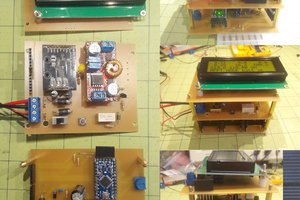
 Tobias
 Dan Julio