Close
0%
0%

Rŏ̽ta

Sticking some nixie tubes on a rotary phone dial

Public Chat
Similar projects worth following
Starting from
$150.00
ArchiteuthisFux has 274 orders / 8reviews
Ships from United States of America
Version 2 now does a bunch of other things, so I've removed the duck part and added some c͓̹͊ǒ͍͢͠m͖͖̈́b̡̼̊i͜n͓i͡n͍͚͒ǧ̌ d̡͌i̫͓ä́͢͡c̼̊r͚͊͠it͜i̹͊c͒̈́š̫͖, so now I present to you, Rǒta.

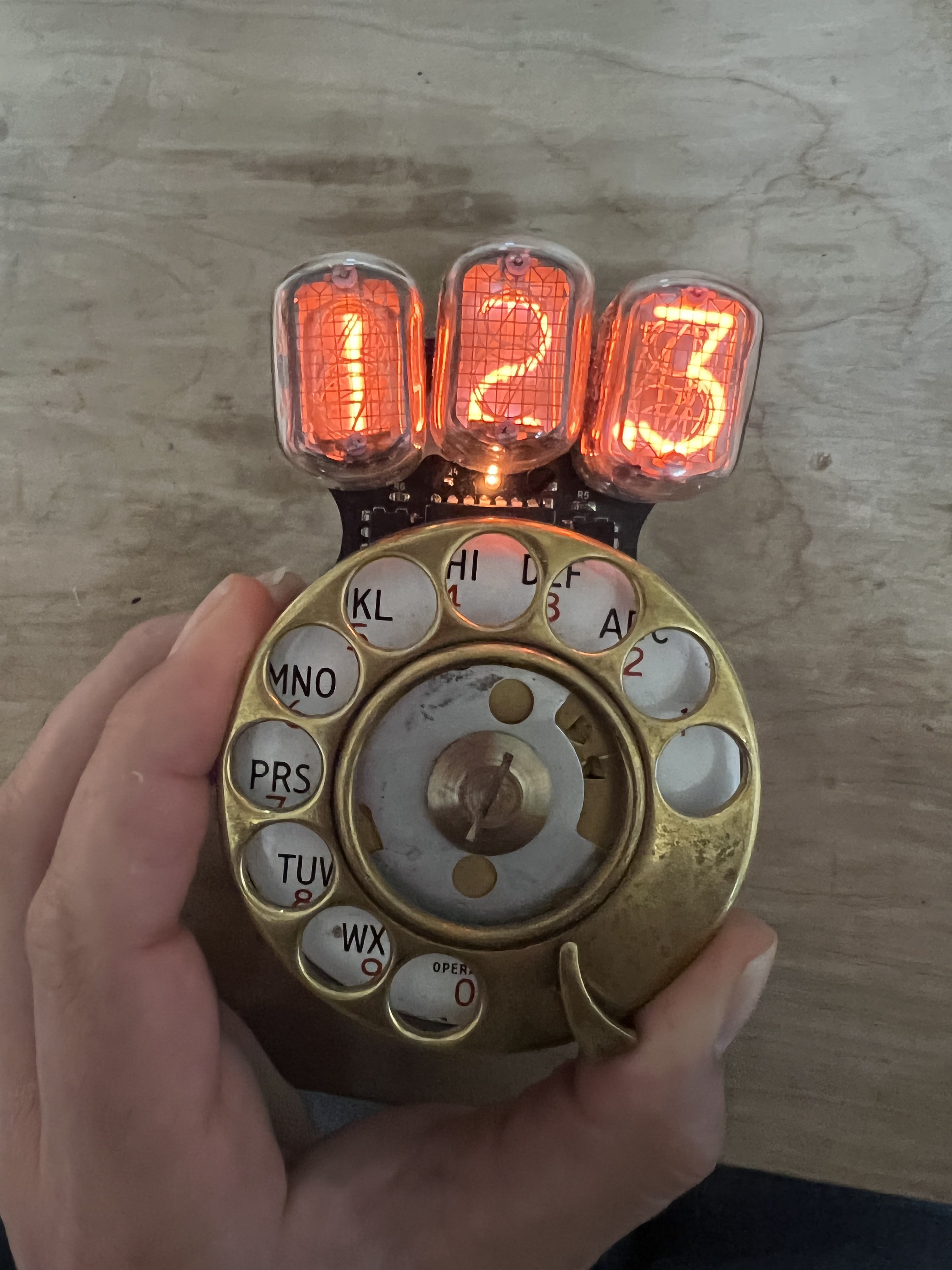
Rǒta is a tool for counting things while being all nerdily extra about it. Are there more efficient ways to count things? Yes. But will those things increase your exposure to Nixie tubes and rotary dials? No? Well then if that's what passes for progress nowadays then I'm going to go live on a mountain somewhere and count things the cooler way, with nixie tubes.

It was originally conceived as a gift for a duck hunting lodge, but now I'm making a few more and I know not everyone is into hunting so it's been generalized.

This is the more complete version of Rǒta
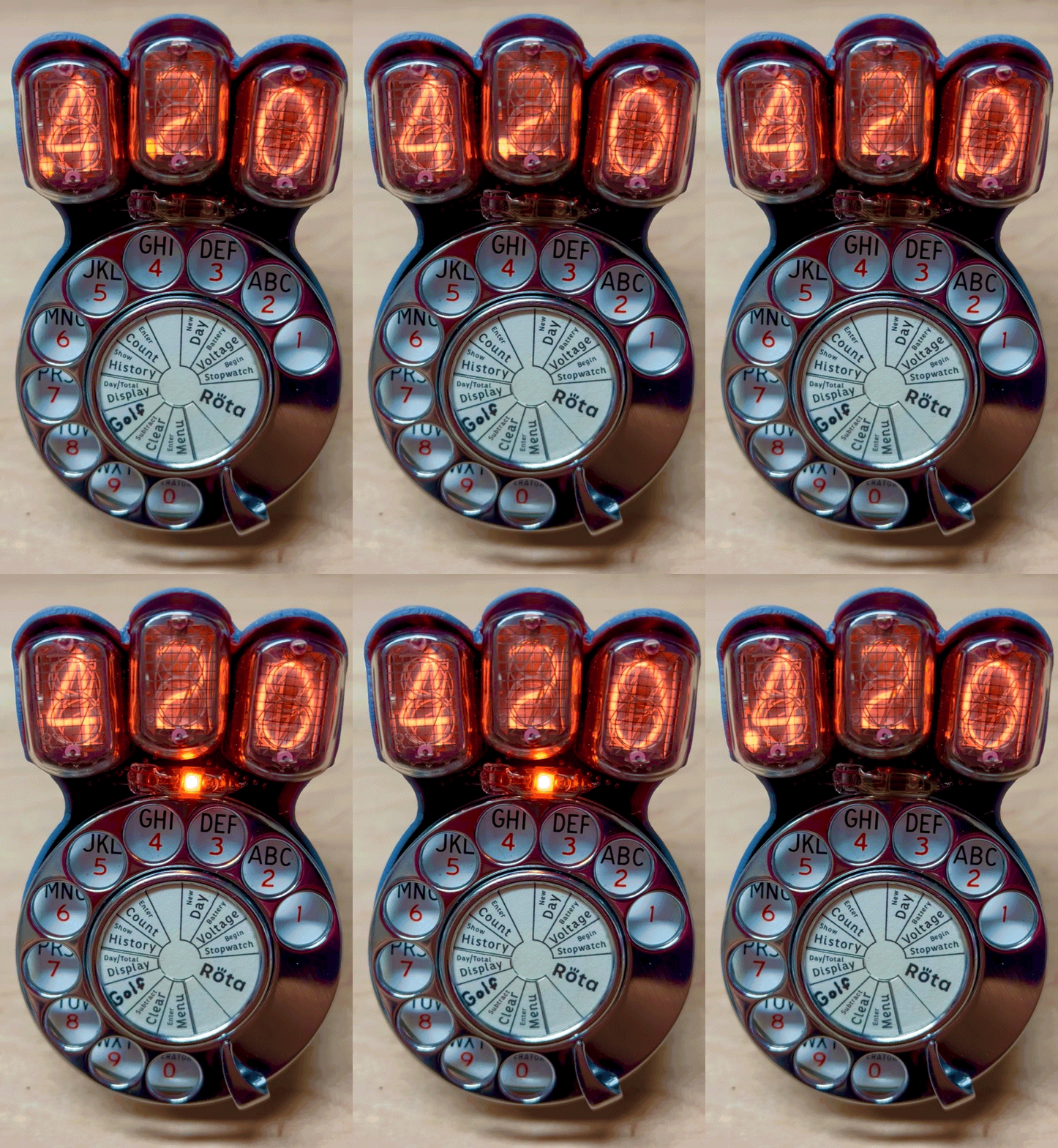
That flashing means it wants your input. These decimal points do way more work than regular decimal points, they tell you a lot about what's going on. When you don't have segments to make crude letters and stuff, you need to get creative with dots.
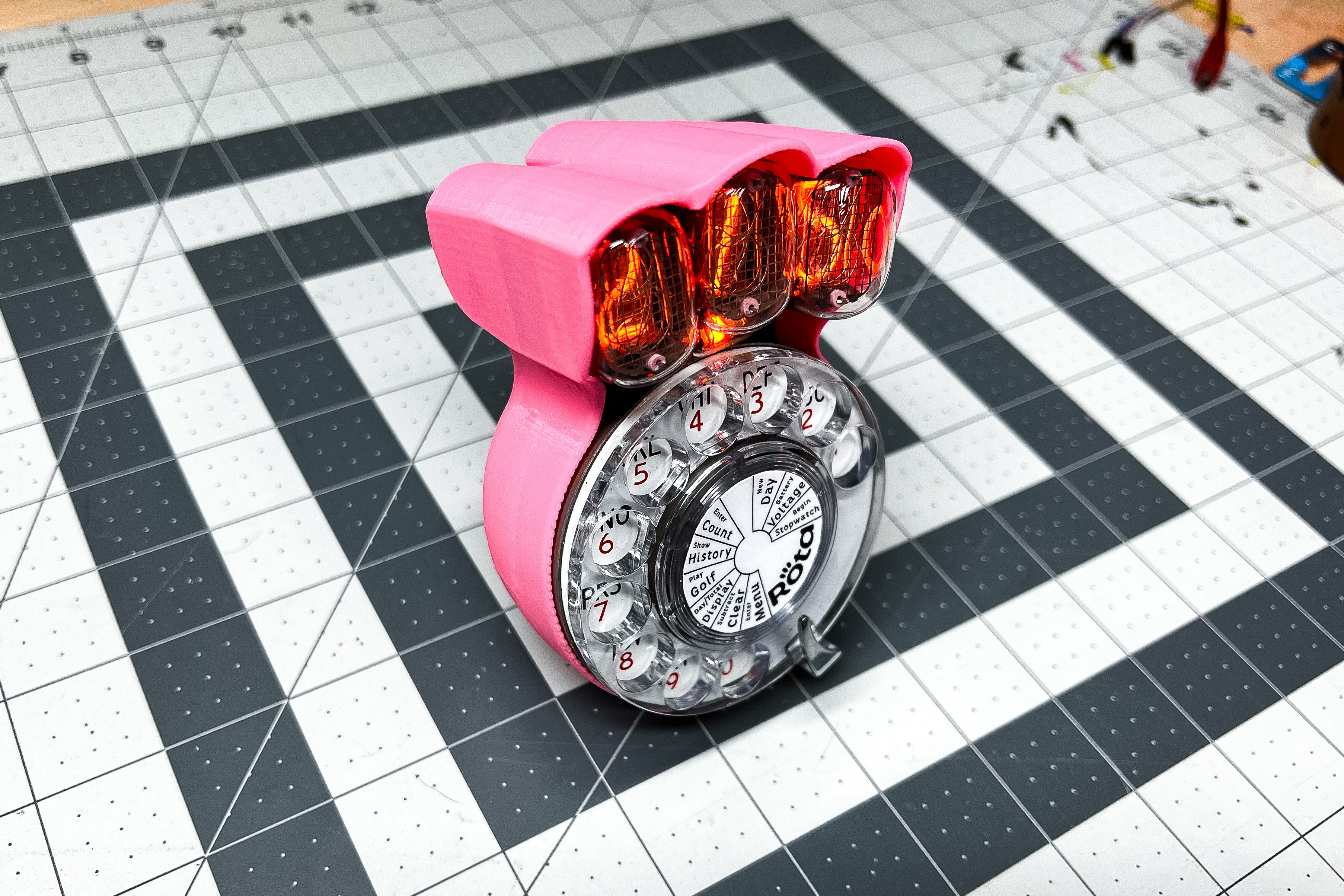
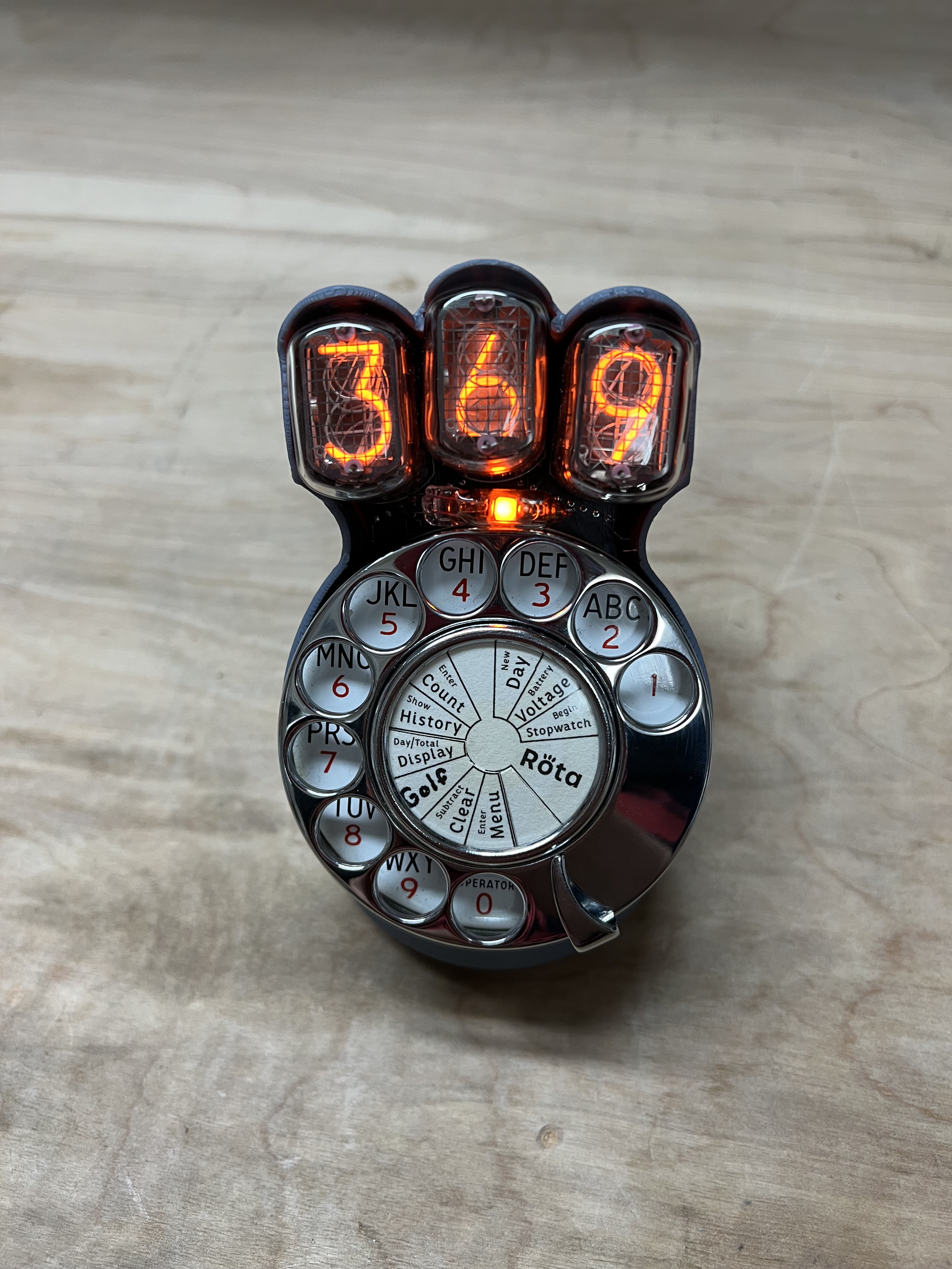
Rǒta is a tool for counting things while being all nerdily extra about it. Are there more efficient ways to count things? Yes. But will those things increase your exposure to Nixie tubes and rotary dials? No? Well then if that's what passes for progress nowadays then I'm going to go live on a mountain somewhere and count things the cooler way, with nixie tubes.

It was originally conceived as a gift for a duck hunting lodge, but now I'm making a few more and I know not everyone is into hunting so it's been generalized into a tool for just counting stuff in general where those $3 hand clickers or a golf pencil just lacks the glamour you need in your life. 

Instead of using sequences of numbers to use the special functions, now you just dial 0 and then the function you want which is printed on the number plate. 

here's the special function menu map

note - I'm calling moving the dial just a little to turn the display on a "click"
when inside a special function, dial anything to exit (preferably 0 because it's only reading intermittently when in menus, so it's most likely to register)

0 -- enter/exit menu or function   shows 111 when you're in the menu)
1 -- stopwatch                    click to start, click again to see last time.
2 -- show battery voltage         briefly turns off the display to get a more accurate reading (not under load)
3 -- new day                      this stores the total since the last time you started a new day. maximum 63 days
4 -- does nothing
5 -- enter a count by digits      enter 3 digits (hundreds - tens - ones) to add to your daily total
6 -- show history                 click through each day with first the day number (on the left) then the total for that day
7 -- toggle day/total display     either shows the count for that day or the running total of all days (default is total)
8 -- golf mode                    keep score for golf - first enter 1-4 players and the decimal points show which player's turn it is
9 -- clear everything             dial 9 again to confirm. dial anything else to go back
999999 -- emergency clear         dial 9 six times to emergency clear everything in case something gets messed up same as dialing 10 9 9
                                  you can also short the middle pulse pin high for super duper emergency clear

If you want to see what these modes look like, here are some videos of me using them,


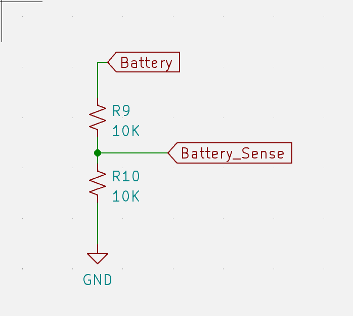
The voltage display was added because I was having issues with the K155ID1s browning out before the HV module (it still blows my mind that it works down to like 3V), so the display would just show all the digits on because the nixie drivers weren't blocking any current. 

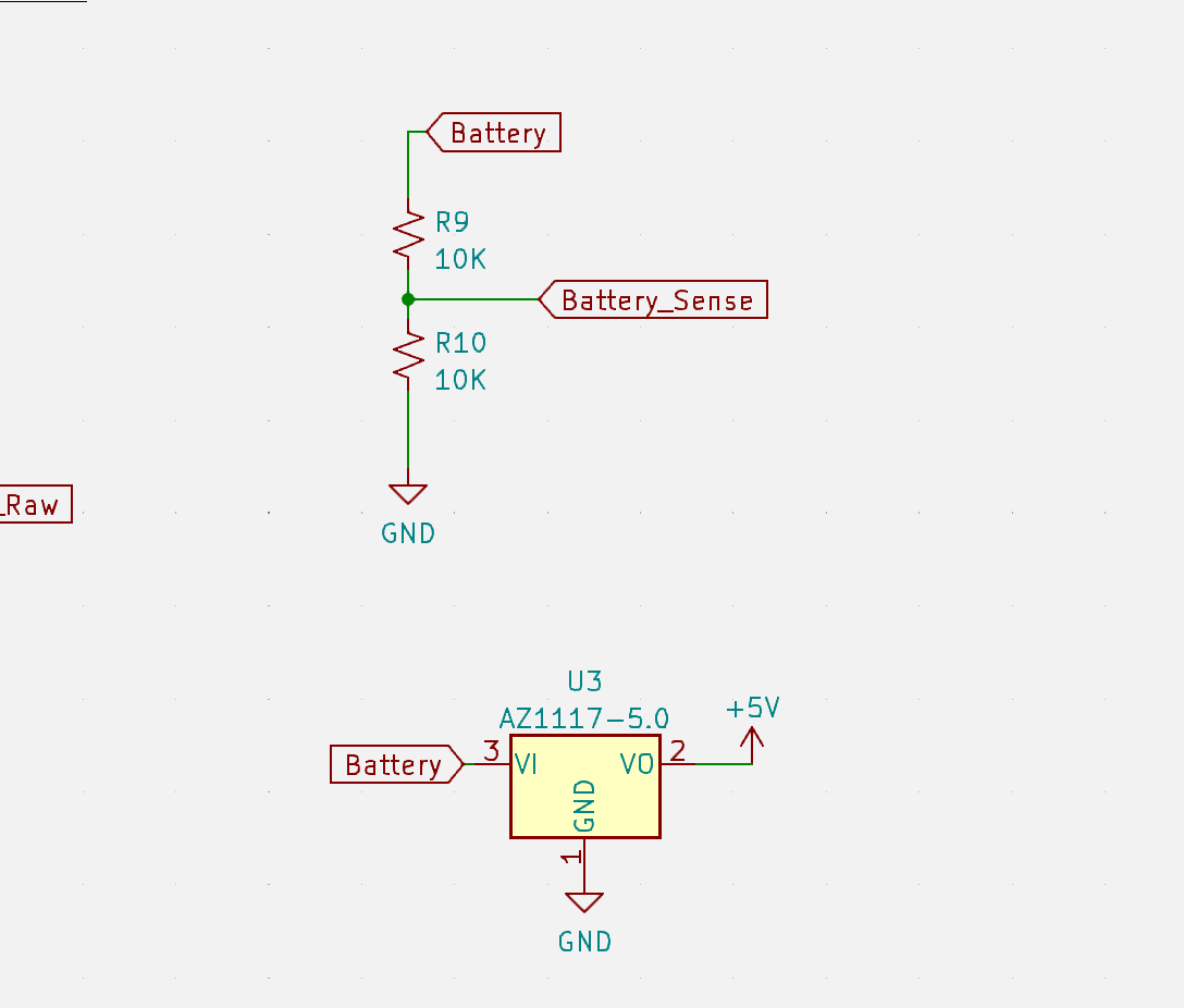
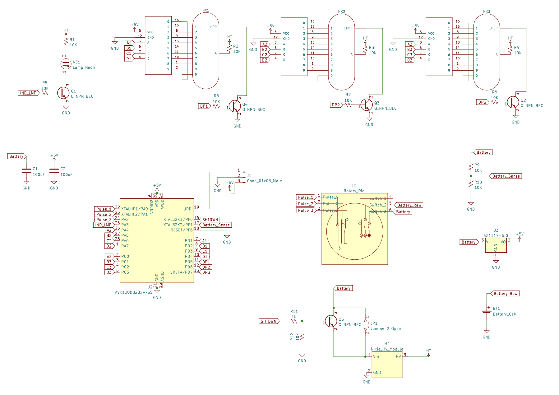
So now I added a HV shutdown and a super simple voltage sense divider that drops the 9 down by half so it can be read by the AVR64DD28's ADC.

The previous 1-transistor version of this was a silly mistake, here it is fixed.
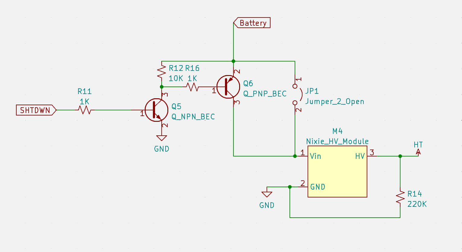
Now if the battery voltage is too low, it shuts down the display but still takes input. In case you don't have a spare battery but still want to count. And the power draw is so low for just the microcontroller that the battery life might as well be infinite.

If you notice in the video, the display flashes when the battery voltage updates, that's because when it does the measurement, it briefly shuts the HV module down so we can measure the battery voltage unloaded. Because this thing draws ~300-400mA when it's on so without doing a ton of math and testing different 9v batteries to correct for it, the voltage it shows would be like ~2V lower than it really is unloaded. 

... Read more »

NumberPlateSheet.pdf

a whole sheet of number plates

Adobe Portable Document Format - 10.77 MB - 10/31/2022 at 20:01

Preview

RotaStenciledBack.svg

in case you want to make a stencil

svg+xml - 501.75 kB - 10/31/2022 at 20:00

Preview

RotaStencilled glow.svg

in case you want to make a stencil

svg+xml - 413.37 kB - 10/31/2022 at 20:00

Preview

RotaBackCase.stl

Back case that leave nixies open

Standard Tesselated Geometry - 1.49 MB - 10/31/2022 at 19:59

Download

rotaFullCase.stl

Full case with covering over the nixies

Standard Tesselated Geometry - 9.97 MB - 10/31/2022 at 19:59

Download

View all 22 files

  • 3 × IN-12B Nixie Tube
  • 1 × IN-3 Indicator Tube
  • 1 × AVR64DD28
  • 1 × Automatic Electric type 24-36 Rotary Dial
  • 1 × AZ1117-5.0 Power Management ICs / Linear Voltage Regulators and LDOs

View all 10 components

  • This is the old description for posterity

    Kevin Santo Cappuccio08/17/2022 at 17:13 0 comments

    RotaDuck 

    Sticking Nixie tubes to an old rotary telephone dial

    This is the old project description, I changed enough stuff that I might as well just rewrite it and copy the old one here.

    Here's a video of it in action

    And there's a few more on my Youtube Channel

    I'll do a more complete write-up at some point in the future, but for now I'll mention a few things.

    It stores the running count (and a history of recent entries) in EEPROM because when the dial returns to it's resting position, the power is completely cut off. That makes it so I couldn't just use timing to figure out when the pulses stop (and the number that was ultimately dialed) so instead I put in a resistor ladder so the between the 3 contacts on the dial to give me 1/2 voltage on the last number, when the dial is between 0 and the end. that gives me a waveform like this:    

         _    _   _    _ 

    __|  |_|  |_|  |_|  |_,-,___ 

     So it does all the saving during that shorter last pulse, which is pretty tight because EEPROM access is relatively slow. 

    I didn't want to add any buttons to it so instead it uses multiple 9s and 0s for special codes, here's the list of what they do 0   - subtract the next number dialed from the total 000 - clear all counts to 0

    9   - show total for all days 99  - list each day and the total for each 999 - start a new day Here's what I'm talking about when I say days. So this was originally designed for duck hunting (hence the duck in the name) as a gift for a duck hunting club. If you want to count how many ducks you got, we'd usually bring one of those mechanical clicker counters and just keep a running total.But I figured if I'm making a thing to count how many ducks were shot during a trip, it might also be useful to have that information separated by days if you want to keep a separate daily and running total. 

    At some point I'll print that menu in the middle of the dial.

    If you intend to make one of these for yourself, you should probably know this thing is like 90% bodges and perfboard circuits. I eyeballed the shape of the dial cutout nearly perfect, except that it's flipped on the board. So instead of just redoing the board like a sane person, I just mounted it with everything on the wrong side and bodged wired a ton of things to make it work. That's why there are those arrays in the code to convert the number shown to the number its actually wired to. So if you really want one, let me know and I can do a version 2 that will be 100x easier to put together. 

    I also made a rechargeable one by dead bug soldering a tiny 10DFN MCP73213T charge controller and putting in 2 1/2 AA sized lithium batteries, but after using it a while, the simplicity of just using a 9 volt battery is much nicer (and lasts a lot longer.)

    Eventually that red wire sticking out will be connected to a barrel jack port. Once I decide on an enclosure.

  • Okay fine, I'll do a Version 2

    Kevin Santo Cappuccio07/26/2022 at 00:45 0 comments

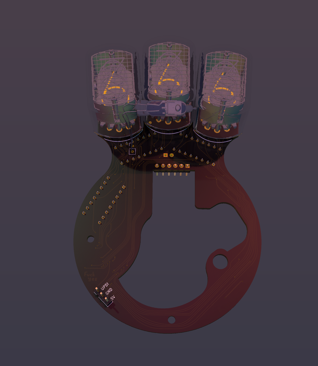
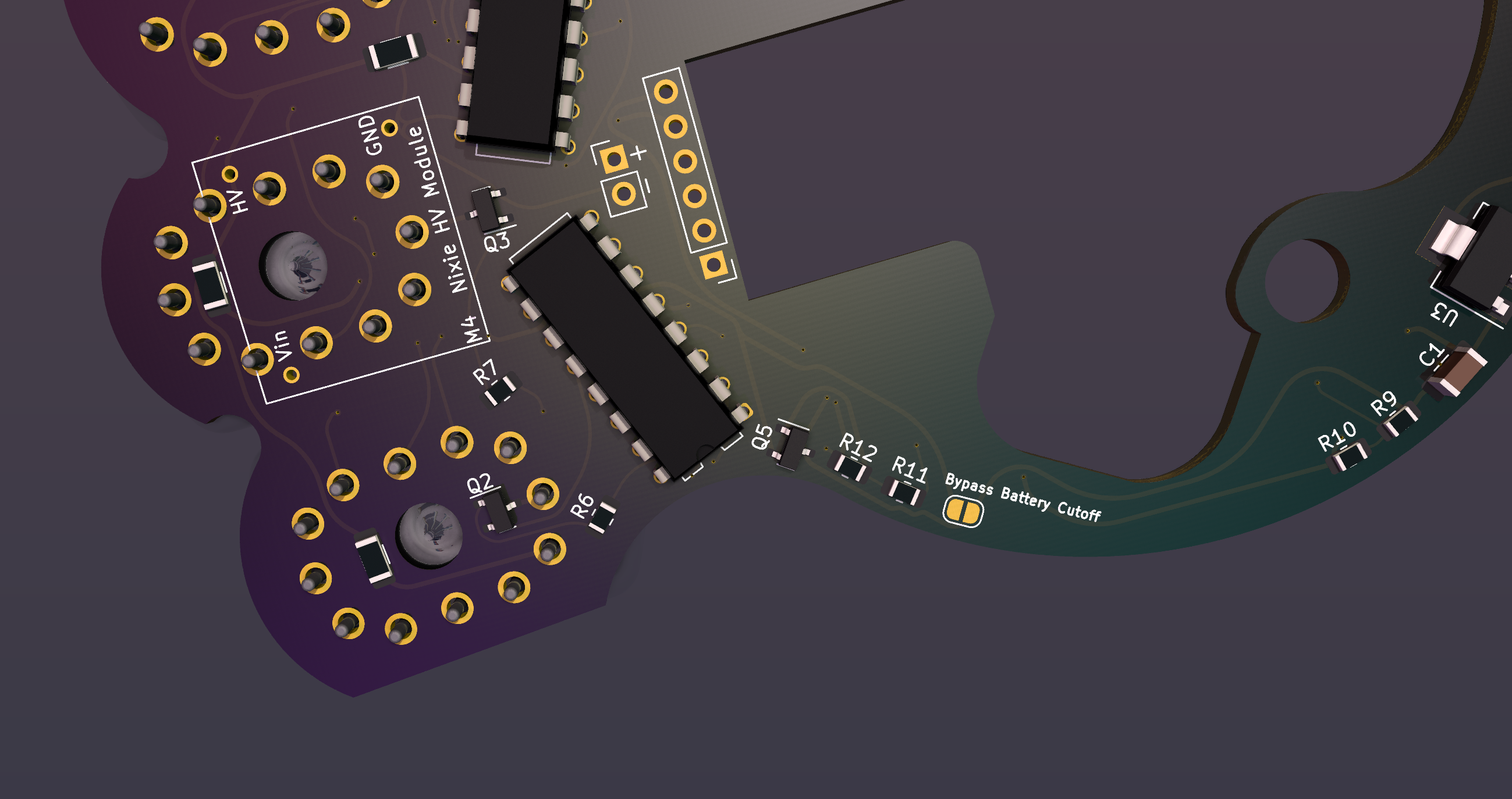
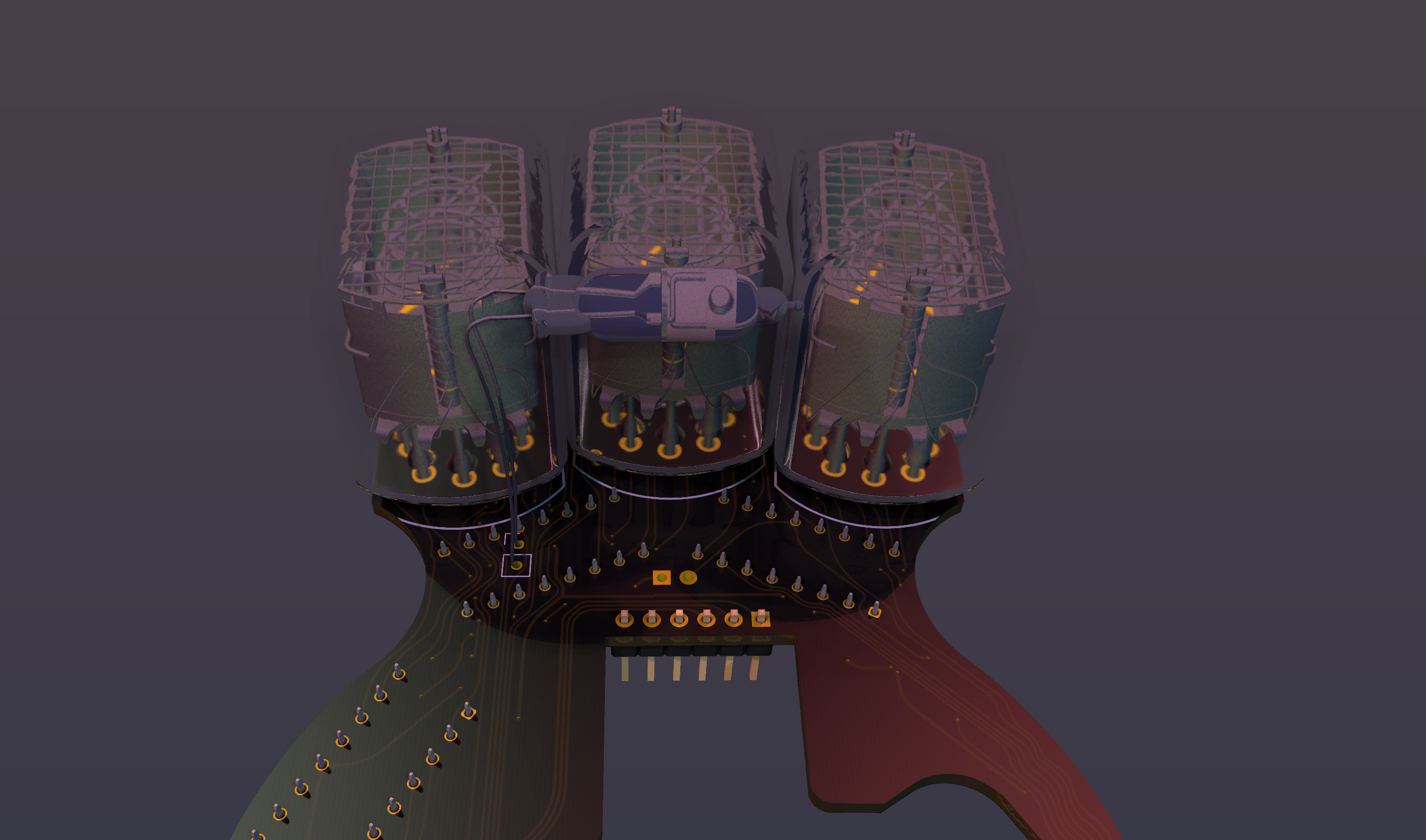
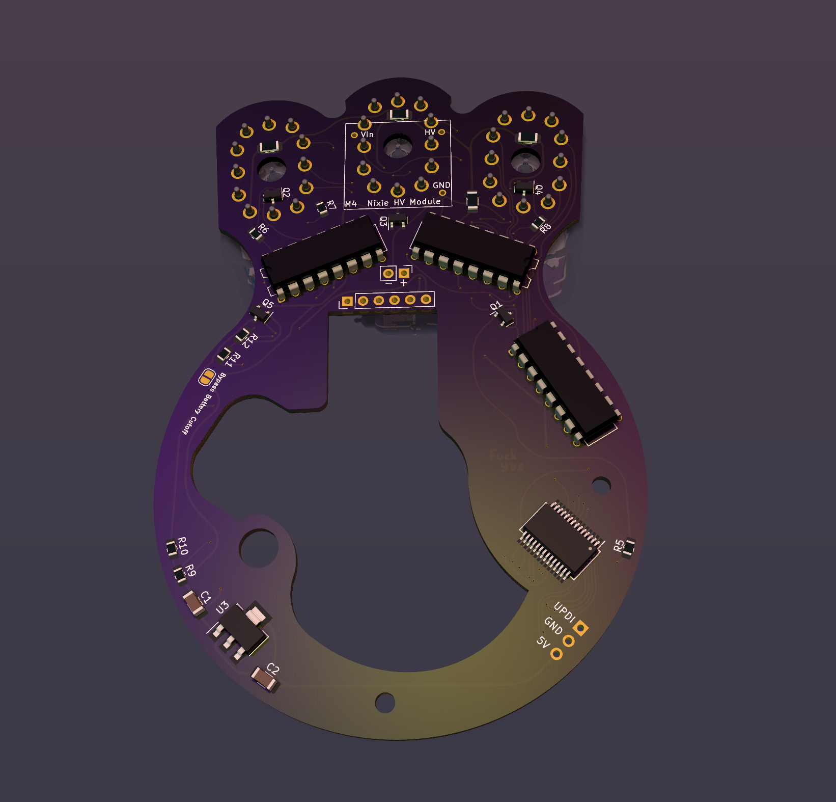
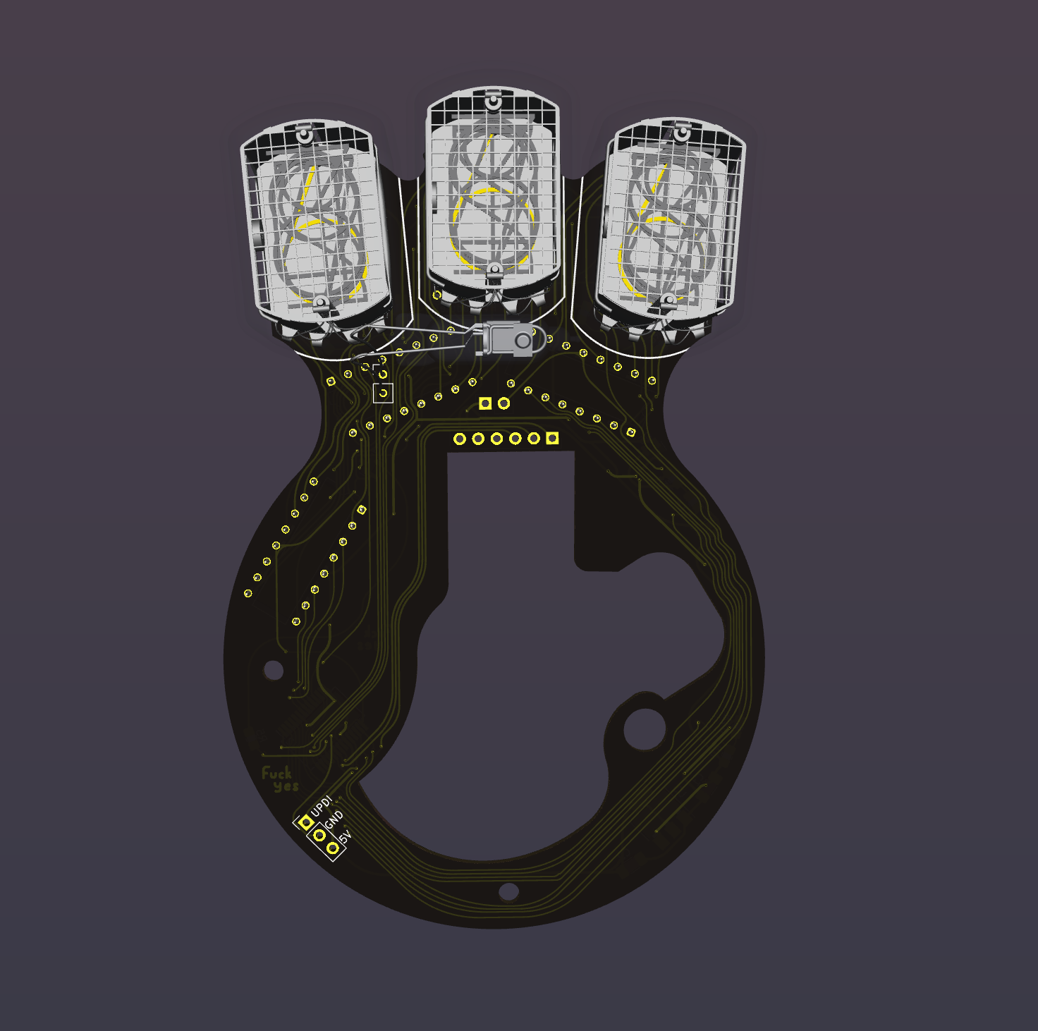
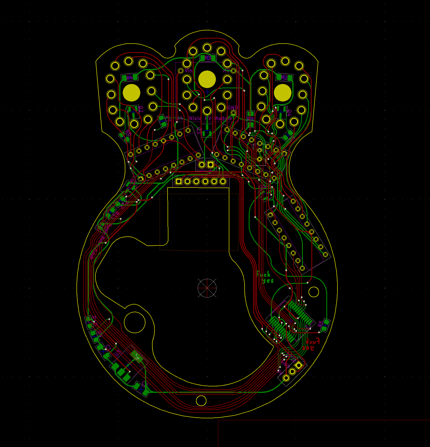
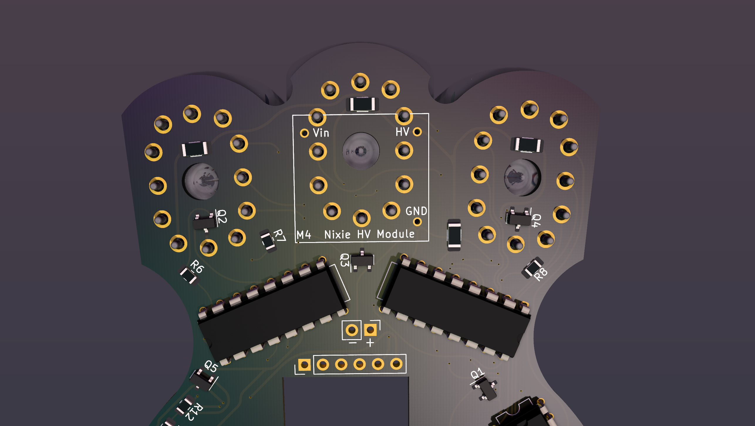
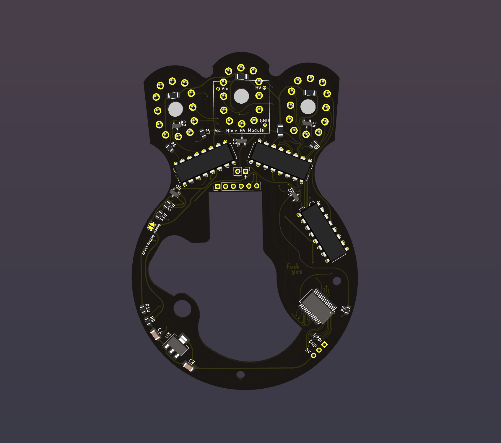
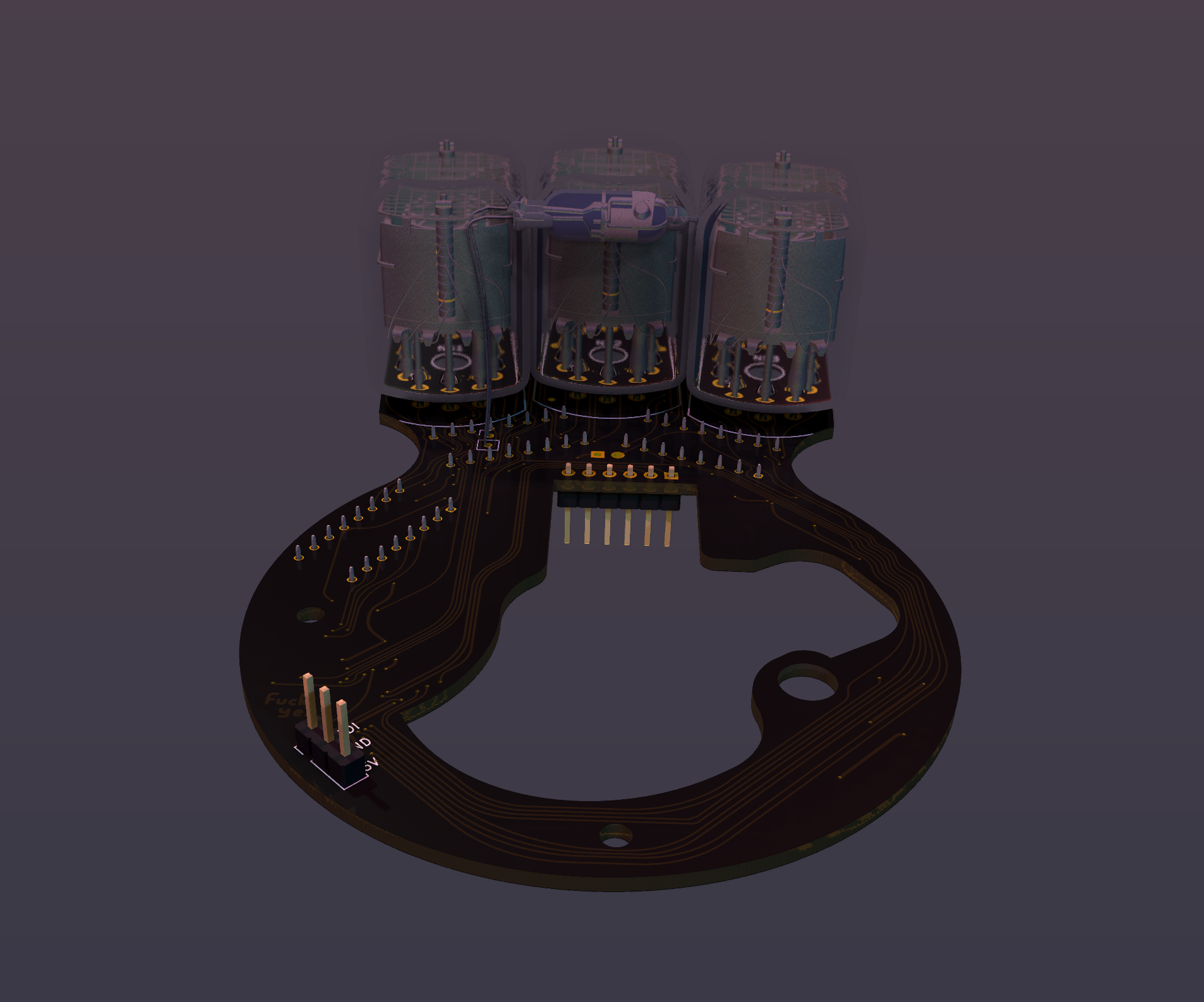
    So I just finished the board for Version 2, and here it is in glorious melty 3D

    Here's a list of the things I've changed to make this something you could actually put together (unlike the last version.)

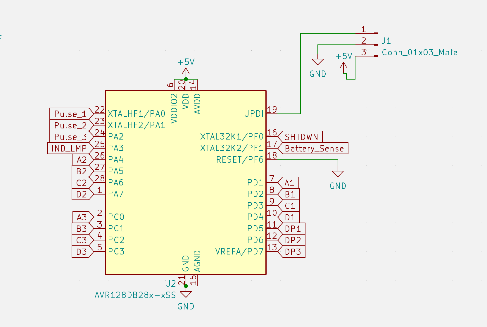
    First, I needed a couple more pins on the microcontroller to make things a bit easier, so I went with the brand-spankin'-new AVR64DD28. It might be overkill for something like this but it's hella cheap, available and I really like the Dx series from Microchip.

    Those few extra pins let me do some things I wanted to do on the first one but lacked the GPIO (and no, I wasn't going to use a shift register.) 

    First, it lets me disconnect the high voltage supply when the battery voltage dips too low. I had that problem on the last one, where it runs the 9V battery down enough that it can't power the K155ID1s (which is crazy to me that they can brownout before the Nixie High Voltage module, it can run down to ~3V) and so the Nixies just show all the digits on in a weird glow. It senses the battery voltage with a voltage divider connected to an ADC. 

    I also added a solder jumper to bypass the shutdown circuit in case it causes more problems than it's worth. 

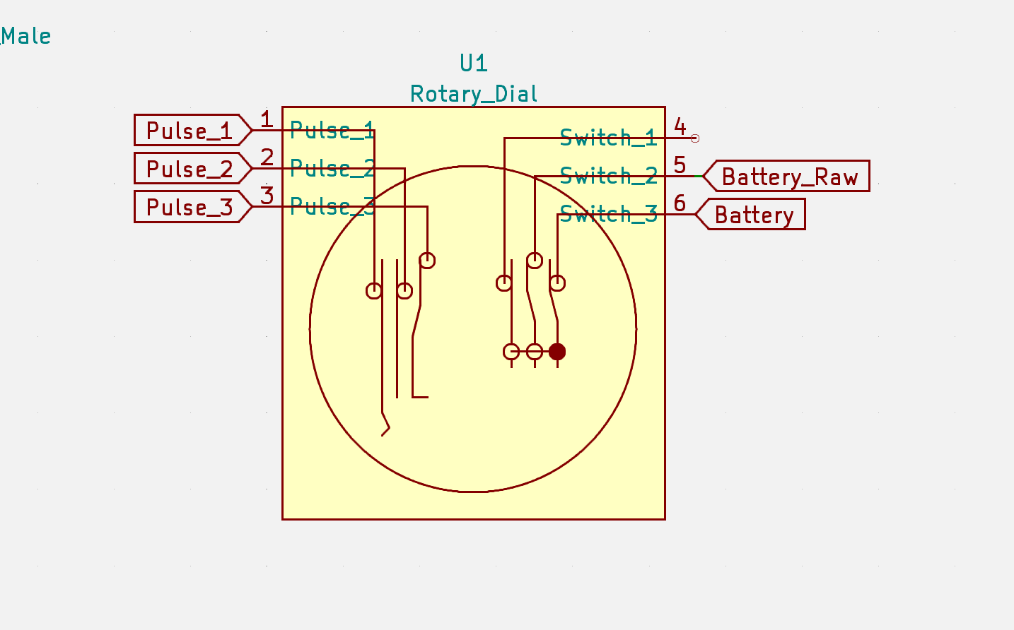
    Also, now I have all 3 of the pulse pins connected to the uC. The hacky voltage divider on the last one was cool, but now I can choose which of the contacts to drive high and sense it on the other 2. Because the pulse signaling seems really simple at first, but I had a lot of trouble wrapping my head around it when it came time to actually code it. It just gets really confusing for some reason. Hopefully this overdone schematic symbol helped. 

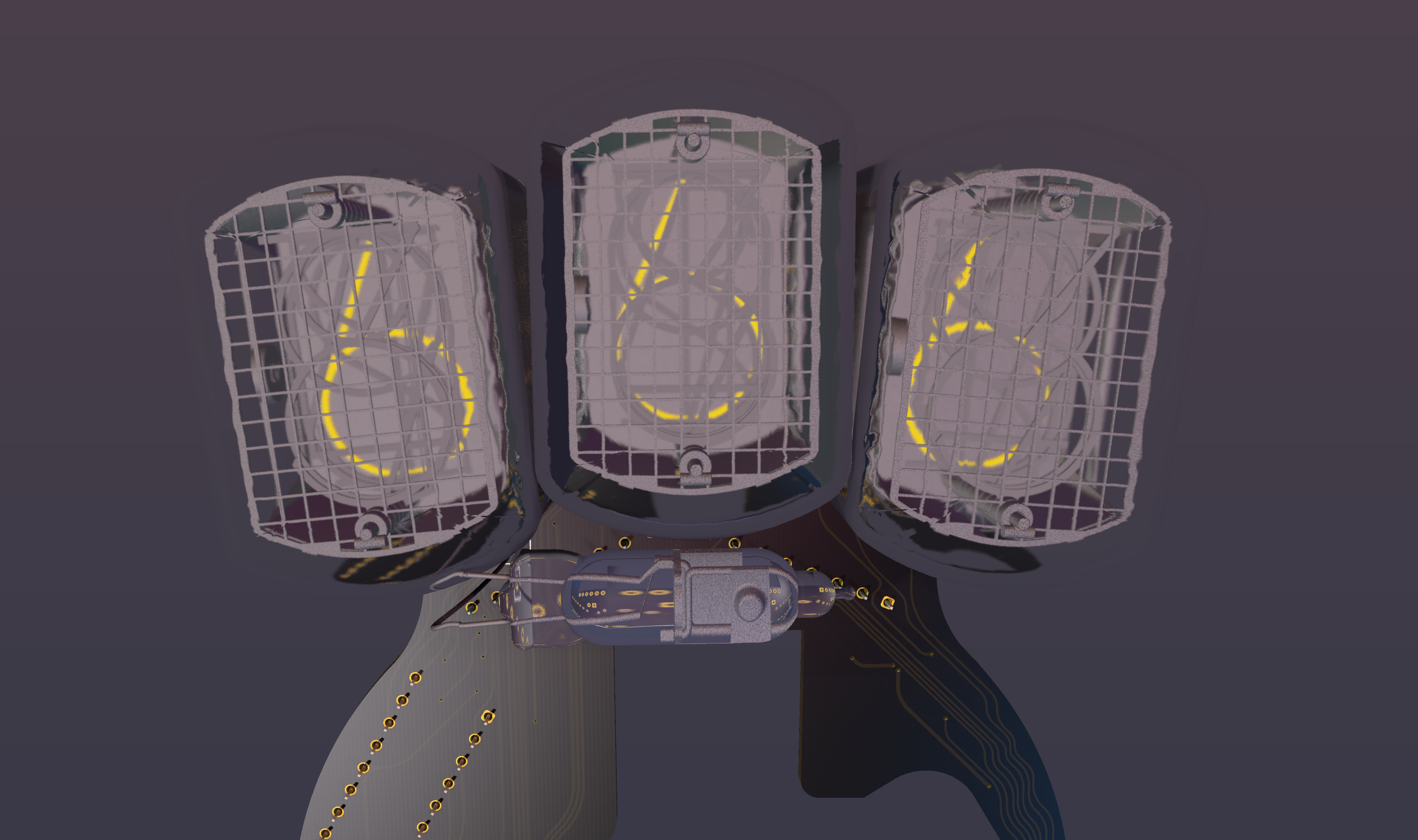
    And now the little indicator light in the bottom middle of the Nixies is an IN-3 tube. I actually put this together on the rechargeable Version 1 I put together, and I like how it looks. I spent a ridiculous amount of time editing the 3D model and getting it into KiCad, but it was all worth it to have this render.

    But most importantly, its super melty. I had to do a few components angled out of necessity, and it looked weird with all the other ones straight. So I leaned into it to keep a cohesive aesthetic. And also rounded the tracks because it looks rad. 

    Anyway, The board hasn't come yet so I can't say whether it works or not, but I'll upload all the files if you're eager to build one of these yourself. And let me know if you are building one so I can walk you through some of the weirdness with how to disconnect the 3 arms on the back of your rotary dial. 

    Here's a few more screenshots

View all 2 project logs

  • 1
    Okay now you can do it

    Now you can go ahead and build this. Just a few things to keep in mind:

    This might work with other dials with a ton of hacking, but the one I built this for is the older style Automatic Electric type 24 dial.  I'm not among the surprisingly large group of rotary phone enthusiasts so I'm not exactly sure what range of models Automatic Electric makes have the exact same measurements. 

    Either way, once you have the dial you'll need to isolate the contactor arms by unscrewing the 4 screws holding them into the square riser, and moving around the little plates of insulator and metal tabs with screw holes to make them separate circuits. I had to make another insulator by just cutting a piece of cardstock (the kit comes with a bunch of extras.) I've messed with mine so many times I don't know how the were originally but that's one of the nice things with old stuff like this, it's pretty obvious what's going on when you see it. I'll take pictures when I assemble version 2 but this should be pretty straightforward. 

    You'll also need this Nixie Power Supply Module which is expensive but these new tiny ones are great. 

    I also haven't changed the code to work with the new version but it should be pretty simple to change it. I'll post that as soon as I get the boards.

View all instructions

Enjoy this project?

Share

Discussions

Pops wrote 08/19/2022 at 14:23 point

Version 2 looks Fantastic !  And I love the fact you took the time to enhance it.  I have already ordered a couple of dials.  I'll wait on the PCB BOM until you validate it!I am absolutely going to build this as I'm always looking for nixie projects that are not just another clock.  I have too many of those already :-)    Again, thanks for posting this project.  What board house did you use?  I typically go to JLCPCB or seeedstudio.

  Are you sure? yes | no

Dan Maloney wrote 08/18/2022 at 23:23 point

Hey Kevin --

Absolutely love the way this looks! Seems like the kind of thing you'd just want to hold in your hand and play with. Great job, wrote it up for the blog, should publish soon. Thanks for the tip!

  Are you sure? yes | no

Pops wrote 08/03/2022 at 19:22 point

Thanks for working on the V2.  That is a PCB I will order.

Very nice nixie project.!!  Thanks for sharing it.

  Are you sure? yes | no

Wolfgang wrote 07/21/2022 at 08:12 point

would be interested too !

  Are you sure? yes | no

Kevin Santo Cappuccio wrote 07/20/2022 at 19:55 point
Alright you've convinced me, I'll do a V2 if you guys are considering building one.

I've been spending a ton of time on breadWare V3 but I might be able to sneak this in while I'm waiting for parts or something.

https://hackaday.io/project/180394-breadware/log/208431-finally-some-progress-on-version-3

  Are you sure? yes | no

Michail Wilson wrote 07/20/2022 at 19:38 point

Love to get the V2 as well.

  Are you sure? yes | no

Pops wrote 07/20/2022 at 15:59 point

YES!  Please do a version 2 for easier assembly !
Super nice project, very clever, glad to see it uses the inexpensive and easy to find nixies.

  Are you sure? yes | no

Similar Projects

Does this project spark your interest?

Become a member to follow this project and never miss any updates