 JP Gleyzes
A long time ago I made a first HDD clock. This video became very fast "viral" not because of the clock itself but because of the noise this clock made... (Today almost 500k views !)
It was a lot of fun but really this clock was totally unusable...
Here it is, you can laugh if you crank up the volume !
I could have stopped here my investigations with Hard Disks Drives but I wanted something quieter (even noiseless) and which could stay in my home without being immediately destroyed by my wife... So something "almost pretty".
The result is this analog + digital clock that I made from another hard disk
My first attempt was this one :
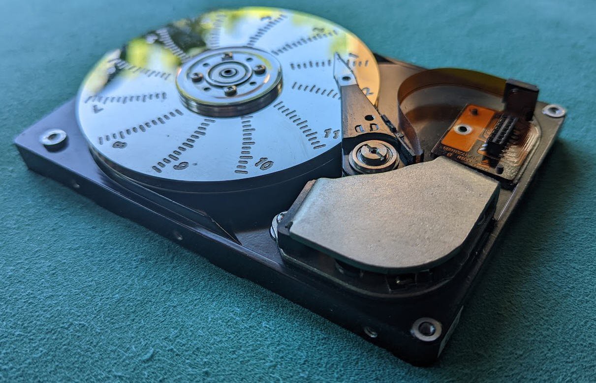
All the inner parts of the drive look like untouched, the arm is fully moving and displays the minutes for each hour. The disk is rotating just every "full" hours.
The motion is smooth and somewhat adictive.
Here is the first video of the clock : we were ten years ago and it was 10:30 am
Now let's see how all this works and how you can do your own "HDD clock".
This project was published on my Website ten years ago, but I will now publish the whole design, the source code, everything in open source and open hardware.
And, If I am not too lazy, I will as well try to port it on an ESP32 MCU and design an android App to get rid of the PC App which is a bit outdated today!
choosing the right disk
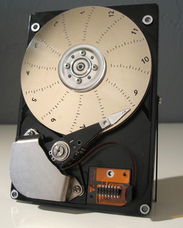
Let's start by choosing the right disk model. Almost any HDD will work but one important thing is mandatory : you must have at least two platters into the disk. We will see why later !
A Hard disk drive is, by itself, a nice "piece of art". It's a precise mechanism with a shining almost perfect mirror.
I decided to keep as much as possible of the original HDD to convert it into a working clock.
My specifications were as follows :
- as little visible modifications on the disk
- the head arm should indicate the minutes
- the rotating disk should indicate the hours
- the device should be automatic on startup
- the disk should be powered by any 5V coming either from a USB charger or directly from a PC USB host
- a USB interface should provide access to a software to tune and setup the device (plug & play)
- Time should be kept in case of a power failure
- clock should be noiseless
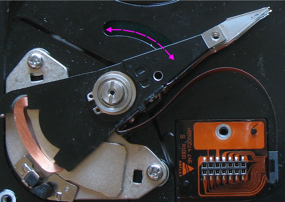
Modifying the heads arm
Wikipedia tells us that a moving-coil galvanometer is a type of ammeter: an instrument for detecting and measuring electric current. It is an analog electromechanical transducer that produces a rotary deflection of some type of pointer in response to electric current flowing through its coil in a magnetic field.
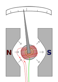 The D'Arsonval/Weston galvanometer used today is constructed with a small pivoting coil of wire in the field of a permanent magnet. The coil is attached to a thin pointer that traverses a calibrated scale. A tiny torsion spring pulls the coil and pointer to the zero position. When a direct current (DC) flows through the coil, the coil generates a magnetic field. This field acts against the permanent magnet. The coil twists, pushing against the spring, and moves the pointer. The hand points at a scale indicating the electric current
Our HDD heads arm is almost a galvanometer but it must be equiped with a litlle torsion spring to convert it into a DIY moving-coil galvanometer.
When I said that this clock would be "analog and digital" I wasn't lying at all... this galvanometer is fully analog. And we will see that the rest of the clock is much more digital!
Adding a position sensor
When the disk rotates you don't know what is its position. As we will engrave the platter with hours marks, we need to have a way to know "where is noon".
A RPR220 phototransistor is soldered on the PCB (details will come) and its led focusses IR beam on the bottom platter of the disk. A hole is drilled in the disk enclosure for that. A dark spot is painted on the disk to be detected easily by the sensor.
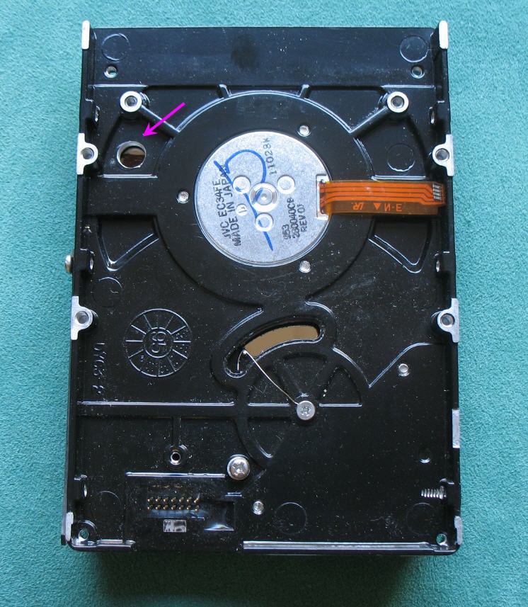
On the left side picture you can see half of the dark spot on the platter.
Drilling this hole is not complex, but positionning it properly on the disk is a little more tricky. Follow these guidelines to add the photo Transistor.
Engraving the disk
To display the hours and minutes you will need to mark the disk.
The best method that I have found is to use a V shape mill and use a CNC.
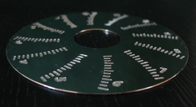
All the details can be found in the "engraving the disk" log
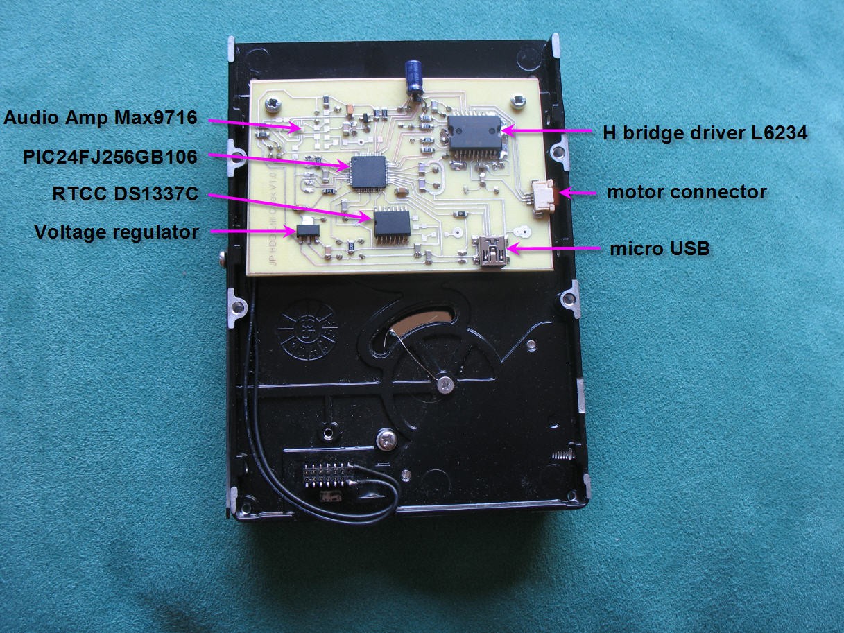
Adding electronics to pilot the disk
Retro-ingeneering the HDD circuitry was far away my competences... So I decided to build a brand new board.
Electronics is based on Microchip PIC 24FJ256GB10. microcontroler. This 16 bits MCU has a native USB port which allows easy interface with a PC.
It has also 9 hardware PWM ports which are perfect to drive motors.
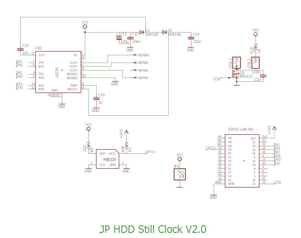
Together with the PIC we find :
- A triple H bridge driver L6234 used to pilot the motor
- a Reflective photosensor (photoreflector) RPR220
- a real time clock calendar DS1337C used to keep time when the power is off
- an audio amplifier MAX9716 for the clock to speak (to be done)
- a 3,3V voltage regulator
- a few SMD components to "make the glue"
![]()
![]()
Please refer to the electronics schematics log for more details.
The eagle files both for the schematics and the PCB are accessible here.
The hardware finished
When everything is mounted, your HDD clock should look like this. You can click on the picture to zoom it!
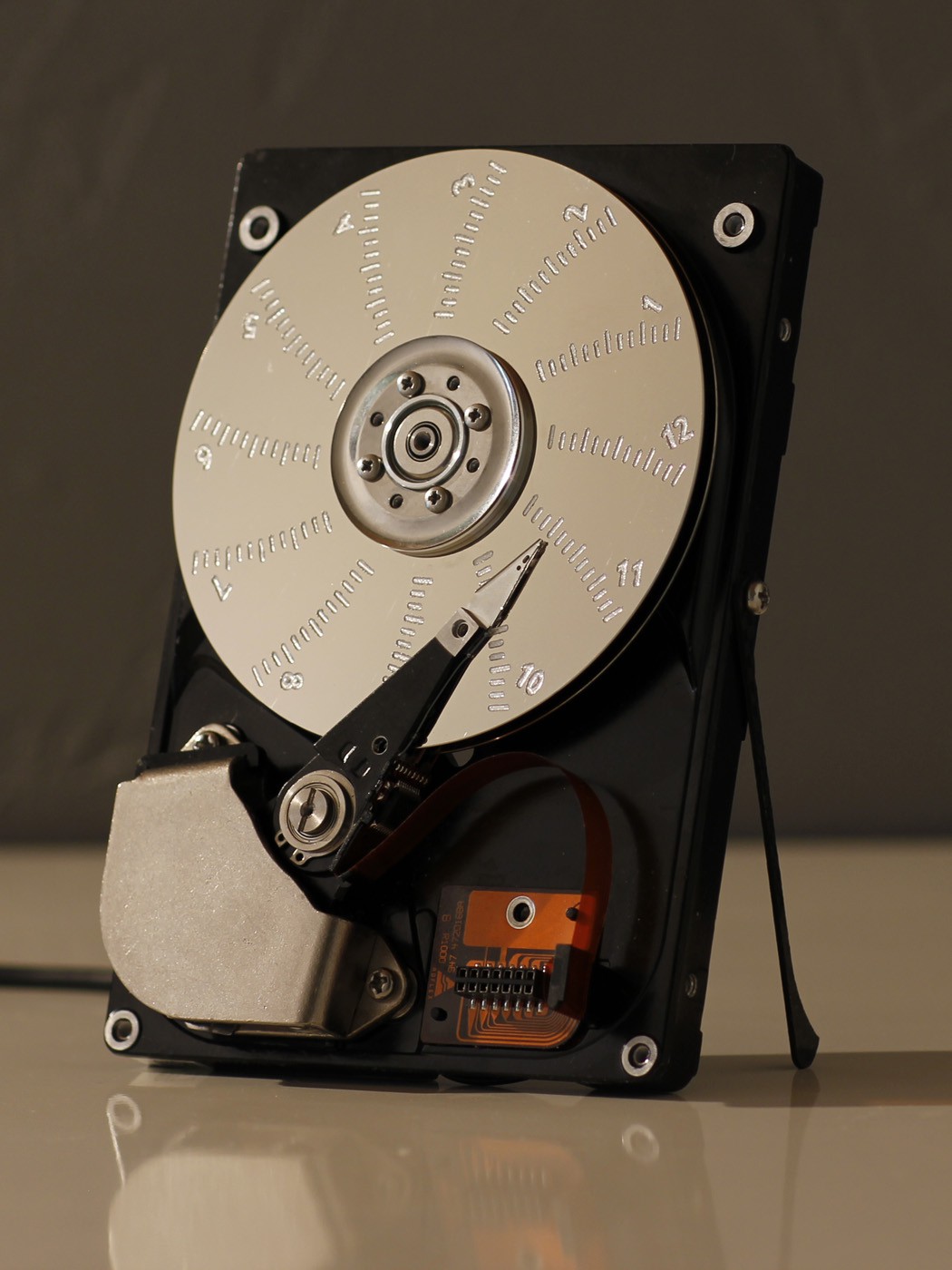
Of course something very important is still missing... The software.
But before jumping into the code we still need to figure out how to drive this small HDD motor and how we can use it to tick the hours...
Running the motor
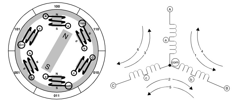
The main difficulty is to run the motor. These devices are brushless Direct Current motors. If you prefer "brushless DC" or even "BLDC" motors.
You will find on internet a lot of interresting readings to pilot a BLDC. Here are my references :
- Brushless DC (BLDC) Motor Fundamentals
- Sensored BLDC Motor Control Using dsPIC30F2010
- Using the dsPIC30F for Sensorless BLDC Control
- Sensorless BLDC Motor Control Using dsPIC30F2010
- Brusless DC Motor Overview (a few drawings on the right come from this link)
A BLDC always has two coils energized and the 3rd one "floating". Considering the various solutions to flow the current into the coils you can get 6 stable positions. This picture shows the motor energized on the first arbitrary position. Curent enters by A point and outputs on B point. The rotor is attracted to this stable position.
I will not enter too much into details here but as you should know more, I highly recommend to read the driving HDD BLDC log.
The software
To run your HDD Still Clock you will need to flash the PIC firmware. .hex file can be downloaded
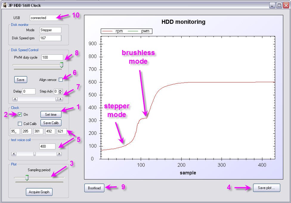
There is also a PC software to fine tune your system. accessible functions are :
- time setup from the PC clock (then backed up into the RTCC)
- switch from "clock" mode to "disk" mode
- monitor disk speed
- save an ascii file of displayed curves.
- calibrate the "minutes" arm
- calibrate the position of the RPR220 sensor
- addmvanced tuning of the motor synchro (steps number increment "Adv" and fraction of step)
- disk speed tuning (PWM duty cycle)
- bootload button allowing to flash firmware when pressing the reset button on the board
- and this board is fully plug and play, no driver is needed on the PC
here is the PC software : download PC software
If you want to understand a little more how it works, the source codes, both for the PIC and for the PC, are accessible on my Github repo
Before using your clock two important features must be described:
refer to the respective logs before going further.
your clock is now finished
Enjoy the time passing!
- Every full hour the disk will rotate
- Every full minute the arm will tick
Porting the clock on ESP32
As promized, I started to port the clock on ESP32 MCU.
Please refer to this log for the schematics
and this one for the PCB
Licenses
Unless otherwise stated, all works presented here that are not based on software/code are subject to the Creative Common Attribution license .
The complete legal text can be found here
Unless otherwise stated, all software/code-based works presented here are subject to the GNU General Public License v3.0
The complete legal text can be found here