 JP Gleyzes
Electronics is based on Microchip PIC 24FJ256GB10. microcontroler. This 16 bits MCU has a native USB port which allows easy interface with a PC.
It has also 9 hardware PWM ports which are perfect to drive motors.
Together with the PIC we find :
- A triple H bridge driver L6234 used to pilot the motor
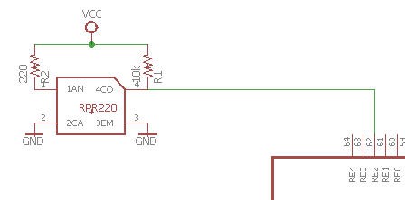
- a Reflective photosensor (photoreflector) RPR220
- a real time clock calendar DS1337C used to keep time when the power is off
- an audio amplifier MAX9716 for the clock to speak (to be done)
- a 3,3V voltage regulator
- a few SMD components to "make the glue"
![]() The schematics are quite simple :
The schematics are quite simple :
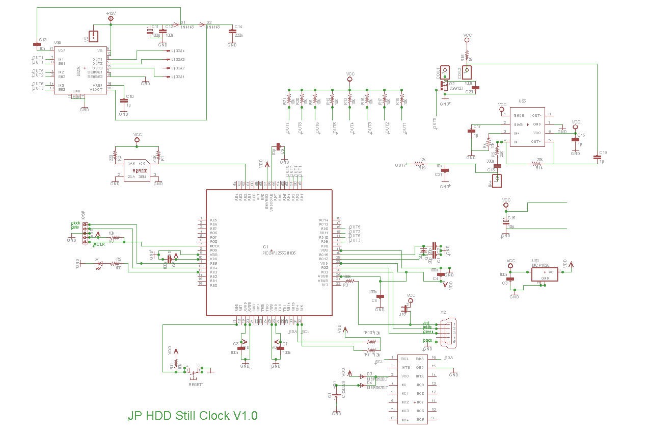
Note that you can safely forget the audio amplifier part which was only added there "for fun" (see the devoted log to be published)

The motor is driven by the H bidge driver L6234
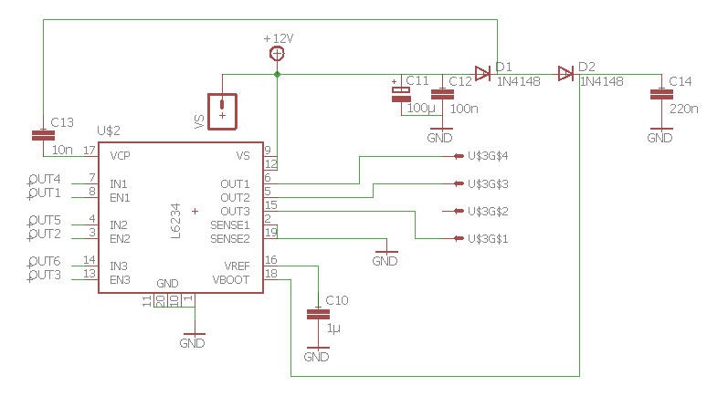
Its outputs are connected directly to the motor connector scavaged from the original board.
Note that VS pin is said to be 12V, but I do power this system only with the 5V DC coming from the USB plug.
It works, the motor is not rotating very fast but it is enough for a clock and the H bridge does not heat at all !
Furthermore, you do not need to add any external power supply, only a smartphone charger !
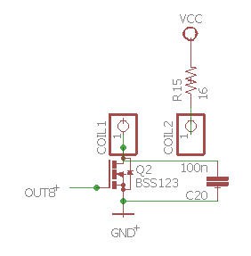
The heads coil is driven directly via a PWM pin issued from the PIC. The Mosfet is there to cope with the 3.3V limitation of the PIC's IO...
Finally the photo transistor is powered at 5V and is connected to a 5V tolerant input pin of the PIC :
That's all for the schematics which is finally quite simple.
You can find all the eagle files including PCB here.
Discussions
Become a Hackaday.io Member
Create an account to leave a comment. Already have an account? Log In.