This is a quick and not-too-dirty tool that does one job well.
The Pi Pico makes it pretty simple and cheap. MicroPython and the IR drivers created by Peter Hinch (github) do all the heavy lifting.
- Download and flash MicroPython to the Pico.
- Download the IR drivers from Peter Hinch's Github repo.
- I used Thonny to access the file system on the Pico.
- I copied the ir_tx folder to the Pico.
- I created main.py with the following code.
from machine import Pin
from ir_tx.nec import NEC
import time
led_onboard = Pin(25, Pin.OUT)
nec = NEC(Pin(17, Pin.OUT, value = 0))
addr = 0xc7ea
dat = 0x17
rpt = 0x6897
led_onboard.value(1)
nec.transmit(addr,dat)
time.sleep(0.5)
nec.transmit(addr,rpt)
time.sleep(0.5)
led_onboard.value(0)
What is the Code?
I needed to know what code the actual TV remote was using to power it on and off. So I started with an Arduino project that used an IR receiver like this one and loosely followed the guide seen here.
Once I had the hex strings the original remote was spitting out, I felt like I had what I needed. I was mostly right about that.
It took some moving puzzle pieces around to finally figure out I needed the "0x" in front of the strings (go ahead, laugh. I'm not a computer science major.) I also had to discover by trial and error that the address and data strings were reversed from the order I anticipated. But once I figured those two things out, it worked as I had hoped it would.
Of course, the code is useless without the hardware:
I used a salvaged IR LED. I used a variable power supply to determine the forward voltage minimum, and selected my resistor based on that. Starting at zero, I slowly turned the power up until I could see the dim red light that IR LEDs emit.
Turned out to be 1.5VDC minimum. I wanted the LED to be a bit brighter than the bare minimum, so I went with 2VDC and 25ma in my calculations. ((Source - fwdV) / current = resistor)
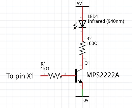
With the 5VDC power rail on the Pico as my supply, a 120 ohm resistor was the appropriate size to go between the transistor and the LED.
Peter Hinch provided this circuit diagram and I followed it, using a PN2222 transistor I had on hand and a 1K ohm resistor between the GPIO pad and the middle leg (base) of the transistor.

I wanted something substantial to mount the components to, but I didn't feel this warranted a circuit board, so I opted to build two busses out of AWG14 copper wire, one for the +5VDC, and the other for GND. You can see those in the pics. The GND bus is soldered laterally across the Pico. The +5VDC bus is insulated along its length, and does a 'dog-leg' through one of the mounting holes in the Pico pcb.
I made a tiny hook in the emitter leg of the transistor and soldered that to the GND busbar.
The two resistors were soldered along the lengths of the base and collector legs, then a small piece of heatshrink tube insulated each of those legs.
I shaped the resistor leads to get to where I needed them to go without touching anything, soldered them in place and I was done.
I soldered a small switch between the RUN pad and a nearby GND pad. This allows me to manually reboot the Pico, which in essence is a way to send the IR code manually. Very nice for testing.
I used a piece of Gorilla double-sided mounting tape to stick the finished assembly under the display near the IR detector, plugged the USB cable into a spare port on a hub connected to my computer. When I power up the PC, the hub gets power which powers the Pico which runs the code which fires the modulated 38kHz carrier out the IR LED and turns on the display.
 Gregory Sanders
 Mountain-Jack

 Robyn W
 Tillo
Tillo