 Guido
GuidoJust to go step by step, before connecting the external ADC, I added an internal RF generator (1 - 30 MHz).
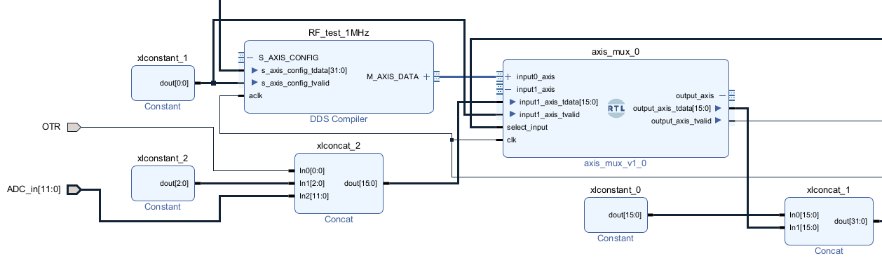
The DDS compiler block with name "RF_test_1MHz" can generate a sinusoid encoded on 12 bits (two's complement).
Using an AXIS MUX "axis_mux_0" you can select (see the line select_input) the real ADC_in or the RF test generator.
Please note that the result is encoded on 32 bits:
- the 1st an 2nd byte contain the 12 bits data sample + 1 bit for "Over The Range"
- the 3rd and 4th byte are 0
In this way I'm ready to handle the IQ samples (16 + 16 bits).
Discussions
Become a Hackaday.io Member
Create an account to leave a comment. Already have an account? Log In.