 Albert Gonzalez
Here I have a fully functional programmable led matrix array I made with a single microcontroller (an atmega48p) and some charlieplexing techniques.
(source code and more info available on github)
It acts as an "external device" that can be attached to a different main micro (even an Arduino-like board with the most common libraries) and also controlled in an easy way via I2C (sending commands to scroll text, control the buffer, the speed, etc.).
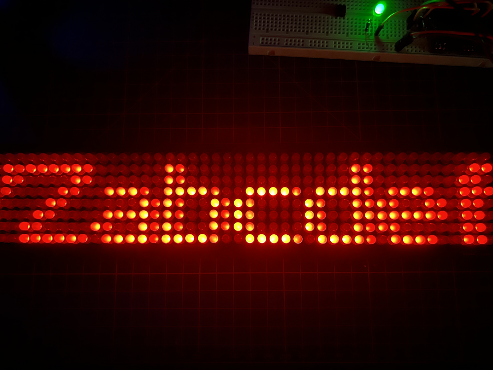
See it in action here:
Led Scroller Matrix Demo! (controlled by an external attiny85 acting as a primary device) pic.twitter.com/aCCRBzYH8c
— Albert Gonzalez, The Isolinear Chip (@isolinearchip) July 17, 2022
Features
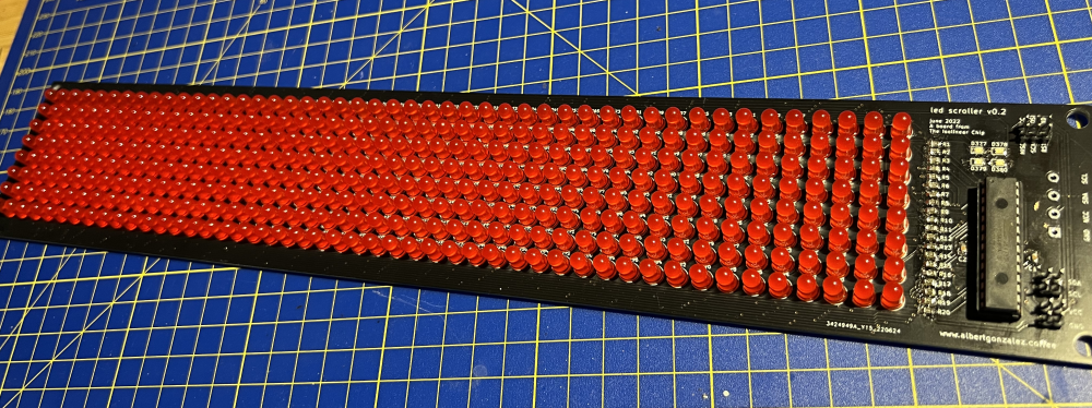
- 376 red leds on a 47x8 matrix configuration
- 4 SMD leds that can act as debug / display / aux indicators
- Small SMD resistors and capacitors to minimize space
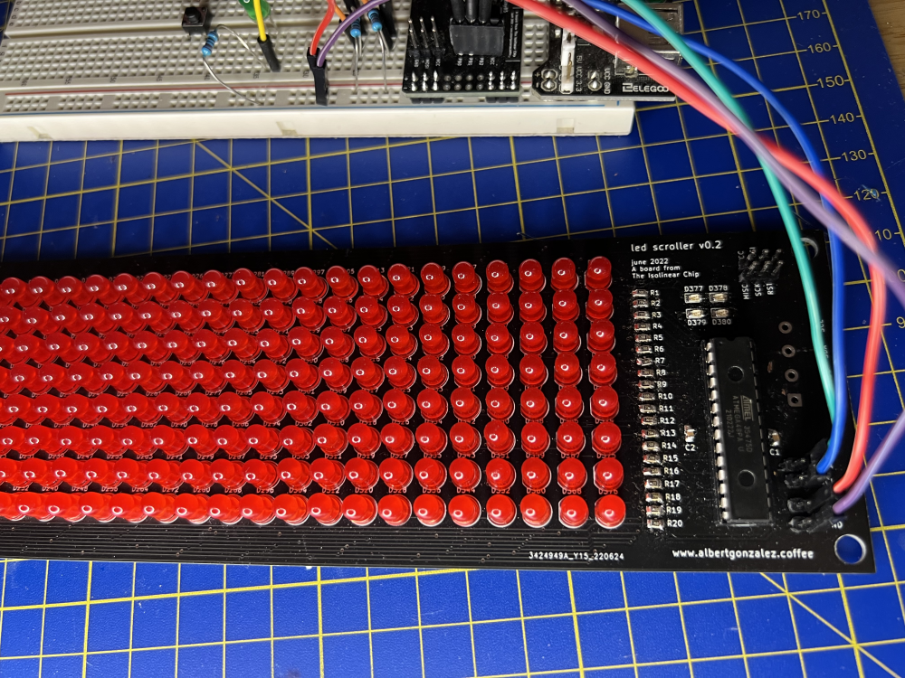
- THT atmega48p (easily replaceable) as the only micro to control everything
- Multiple power / I2C breakouts
- ISP programmer breakout (which won't work due to a short between the leds and some of those pins :_ D - as a future TODO I'll probably add some small switches to disable the leds while programming)
- Different modes of operation: self-test / diagnostic, full buffer control or auto-letters mode with built-in scrolling
- 95 different standard chars supported when displaying letters, numbers and symbols
- Several options available (also commands to be used via I2C): text without scroll, negative mode, variable speed...
- Source code easy to modify (also adding new modes of operation)
Why charlieplexing?
It's a cool and interesting way to drive multiple leds using a small amount of pins and almost no aditional components / multiplexors rather than the main micro and a bunch of resistors.
By using 20 pins from an atmega48p (that's every "regular" I/O pin except the ones for the I2C communication) it can drive up to 380 different leds (n^2 - n, with n = number of pins). If the micro speed is fast enough (the atmega48p here is clocked at 8Mhz with works with no problem at all) and with some software tricks and delays it'll show a very nice and "stable" matrix that allows a pretty decent display.
Charlieplexing issues
Despite being functional, it's far from being perfect (specially if we compare it with non-charlieplexing solutions). There're some "problems" or, at least, minor inconveniences to be aware of:
- The brightness of the leds is significant lower since they're only "active" for small periods of time (by testing different leds I found there're some brands or models that aren't brighter enough, but usually everything will work pretty fine with some delay between each cycle).
- Since all the leds are connected to the same pins in different configurations, if one "fails" or shorts, the whole "block of leds" for that specific pin will start acting weird.
- It'll probably have some peak currents issues if the matrix gets bigger. Since this is a "small" one I didn't experienced any problem, but remember: we're turning on and off the leds at high speeds!
So, in conclusion: it'll work nice for small projects, but if you're planning to build a super-giant-sized matrix you should probably consider a different option (nothing new here :D)
Why I2C?
Following the spirit of those small peripherals that are connected via I2C (OLED screens, real-time clock boards, etc.) and since I'm kinda comfortable with it (even wrote some I2C libraries for attiny85-like AVR micros) I've decided to use it in order to listen to commands and data. This way any main device can just send whatever buffer needs to be displayed, or even use the built-in text-scroller function!
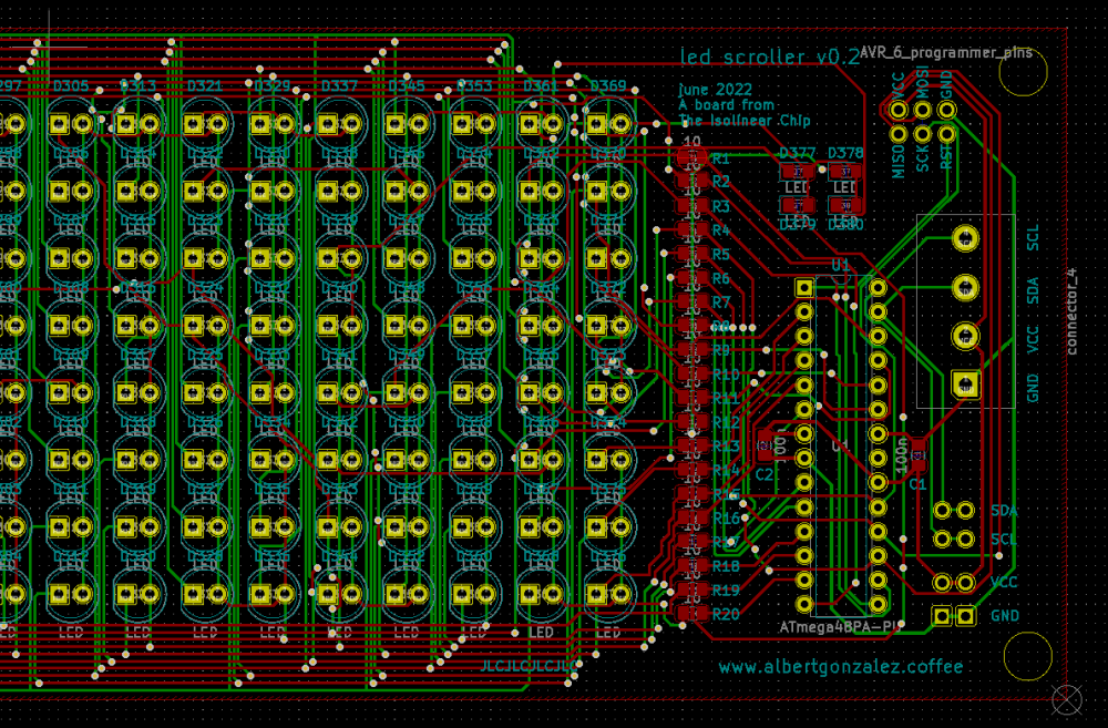
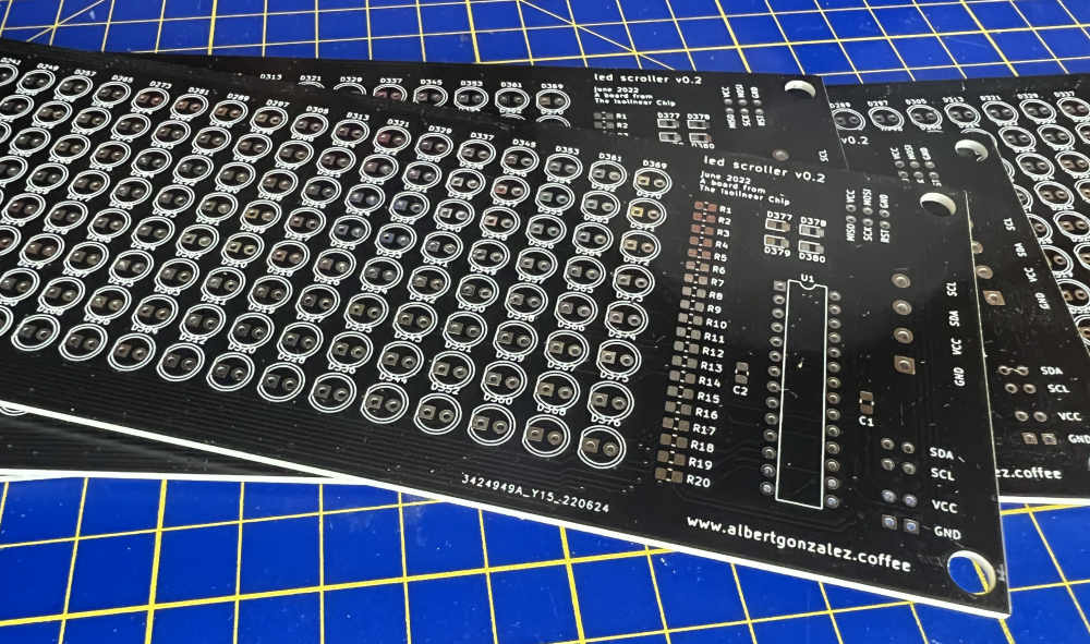
The PCB
The PCB is a homemade design, currently on it's second iteration (the first one was pretty much the same but with more space between the leds, no SMD components and some critical design errors when mapping the resistors with the pins :D) and it's made with KiCad.
It's a big matrix of leds manually wired to a bunch of 20 ohms resistors that goes directly to the 20 atmega48p I/O pins. There're some breakouts for the I2C SDA and SCL lines, the VCC and the GND and some ISP programmer pins too (which cannot be used in this revision once all the leds are soldered due to some shorts between them and a couple of ISP signals :_ D).
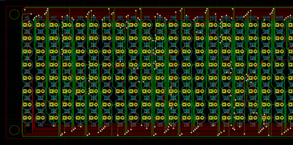
The most difficult (or at least time consuming) part was to manually wire all the different leds to it's different paths on a 2-layer PCB. It's something that can be done, of course, but it takes a loooot of time and requires some organization skills in order to avoid ending up with a messy blob of unhandled vias.
(also solder 376 THT leds takes a looooot more time than I expected!)
How it works? The code
With all the leds properly wired and everything on it's place there's an internal led_status buffer that contains information about each column (since each column is made of 8 leds/pixels, a single byte is used to store it - higher bits for top, lower bits for bottom).
Once everything's set up accordingly there's an endless loop of iterations over this buffer and, for each led/pixel, the proper pins are turned on and off (only on those that are supposed to be "active", of course). Do this fast enough and the ilusion of having everything glowing at the same time will be real (at least for a human eye!).
There's also a timer set on a variable speed (controlled via I2C commands) that can trigger changes on the operation mode and also controls how each mode modifies the buffer once in a while (this modifications are the text scrolling, buffer changes, etc.).
By using the Two-Wire Interface capabilites on the atmega48 the device also listen to I2C commands and performs each action accordingly (turning the display on/off, changing the speed, receiving a string buffer, etc.).
More info on the github repository!
The modes
- The diagnostic mode shows a single glowing pixel traveling all the columns and rows at a reasonable speed. It can be used to make sure all the leds are working and there's no problem with the board.
- The letters scrolling mode receives a bunch of chars that can be set to a specific text buffer automatically displayed and scrolled on the matrix (the scroll option can also be disabled if you just want to display static text). There're 95 different ascii characters encoded in the code with a homemade font.
- The buffer mode allows changing the buffer itself by sending bytes of "pixels" instead of letters. It gives ultimate control over the whole matrix and anything can be displayed by using it!
Issues while writing the software: Wire.h limitations
My first approach when editting the buffers (both the letters one and also the matrix-itself) was to send a fixed amount of stuff (47x8 pixels or a previously set string count) and reset everything each time a new "batch" of data was received.
It worked flawlessly, actually.
But when I switched from a single attiny85 (my test "host" device) to an Arduino (I also wanted to try the Wire.h libraries in order to make the device as "standard" as I could) I noticed there was a limitation on the internal I2C buffer size the Wire.h library uses!
So unless I wanted to have internal 32 bytes buffer too (this means a non-editable full buffer and strings around 30 bytes) I needed to change my approach...
Commands with index + length
Instead of sending everything, now you need to set an initial point on the destination buffer + the length of the data you're transmitting. This allows on-the-fly buffer edition and multiple updates on different parts on the matrix / string.
For instance, you can split a long string into different < 32 bytes chunks or even modify only a specific region on the matrix buffer instead of overriding the entire thing!
Future improvements and TODOs
- As commented before, the ISP breakout on the board doesn't work when shorting a couple of pins with the leds connections. Future board revisions will include a way to temporary disable those connections or the proper fix to allow on-board programming
- As usual with all my projects, I'm working on an enclosure for the board, but my progress there is sloooow :_ D
- More improvements, optimizations and probably bug-fixing on the code is almost mandatory
The development board
Before this board (somehow a "final" or, at least, "usable" version) I made a first testing board to make sure this idea would work. It's a dev-board with more breakouts, no SMD components and leds packed in 10-columns groups.
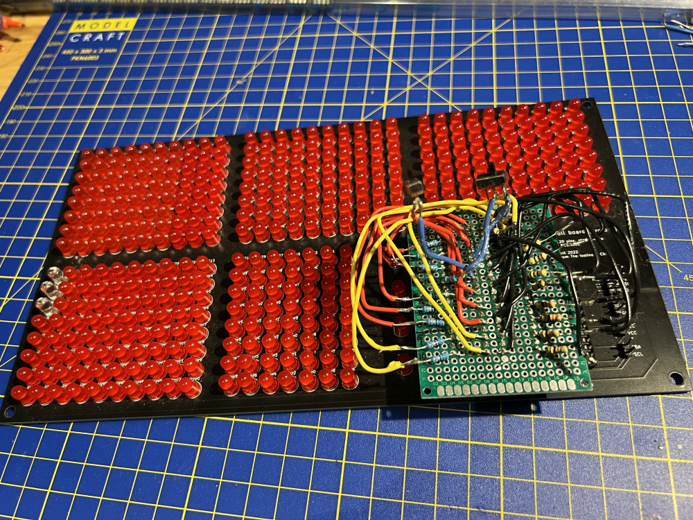
(also notice the external wire chaos I added because I messed up the leds - resistors - pins connections and it needed a manual rewire - which I preferred rather than a software fix, since I wanted it to be closer to a hypothetical final version. There're also a pair of switches to disable the messy pins when programming the micro via ISP).