The latest plan is a PETG frame which slides on to a GU-24 adapter. It holds 2-4 bare circuit boards from common 15W lightbulbs. The idea is to get them to last as long as possible by reducing them to the minimum amount of heat. They'll be in parallel. A transistor is added to the DC side to turn them off & apply PWM.
They're mounted on a common metal heat sink. The bottom is covered in acrylic to protect animals who open the enclosure. A common USB charger provides 5V to a 433Mhz radio receiver which provides the enable voltage.
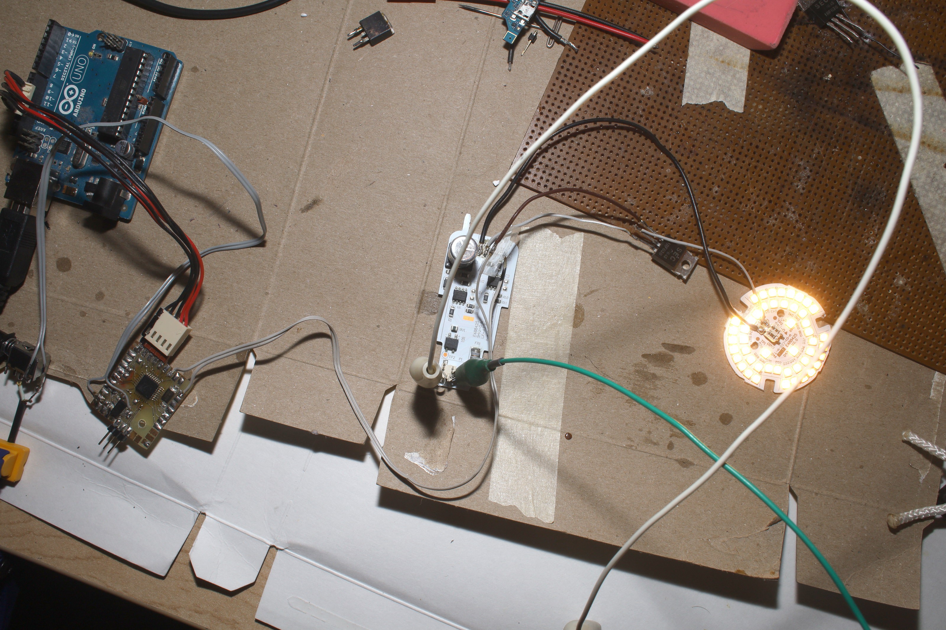
A quick test showed the LED bulbs can't be wired in series to reduce their brightness. At 116V, they can be reduced to 7W but nothing that would make more light than heat can drop the voltage. The only way to underclock is parallel with PWM.
Ground for the 5V has to be the same as GND for the LEDs. GND for the LEDs goes to neutral through 100k. The MOSFET has to withstand 200V or it'll leak. The 15W uses a BP5118F regulator. There's no pinout for the BP5118F that would give an enable pin.

There was a test with 1khz pwm banging a MOSFET on 25% of the time.

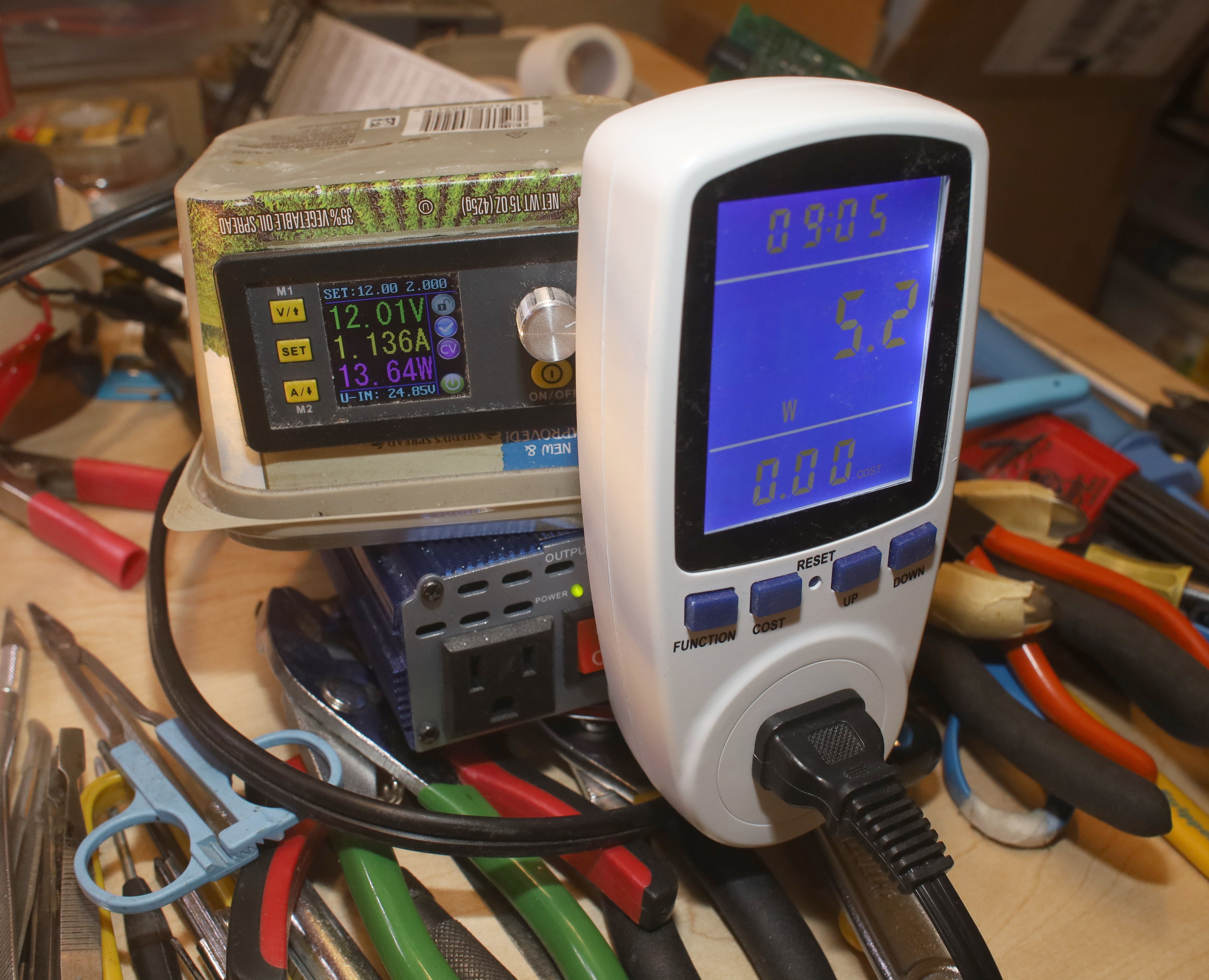
This burned 4.5-5.5W, rising as the LED temperature rose. It seems the current regulator compensates for PWM by allowing maximum current. It would need a heatsink & cooling fan to have any chance of hitting 7.5W. At 33% duty cycle, it gets hot pretty fast & burns 7.5W. At least it showed any light can be made dimmable by modulating the DC ground.
The Riden showed 14W because the power meter & the inverter suck amps. Lions are the only animals who use a current limited inverter for testing 120V. Gootubers plug directly into the 15A wall to get the likes.
 lion mclionhead
Discussions
Become a Hackaday.io Member
Create an account to leave a comment. Already have an account? Log In.