This is the beginning of the design improvements and justification using fluid simulation, CFD. Using OpenFOAM these images are just an illustration that the simulations are working.
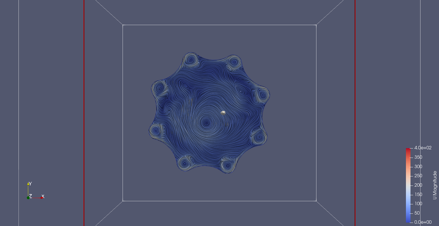
Z-axis slices with Line Integral Convolution, LIC to show air movement.
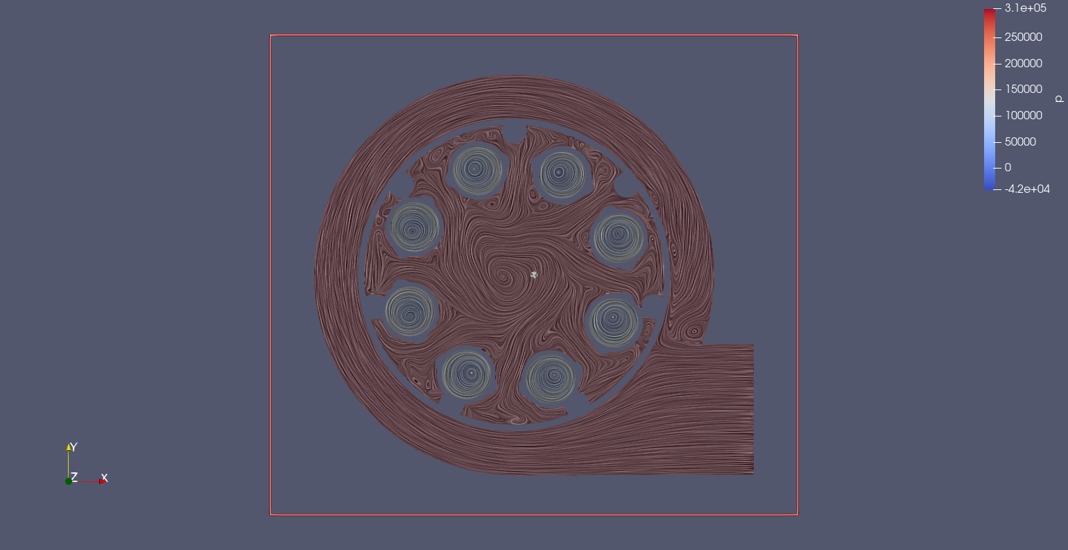
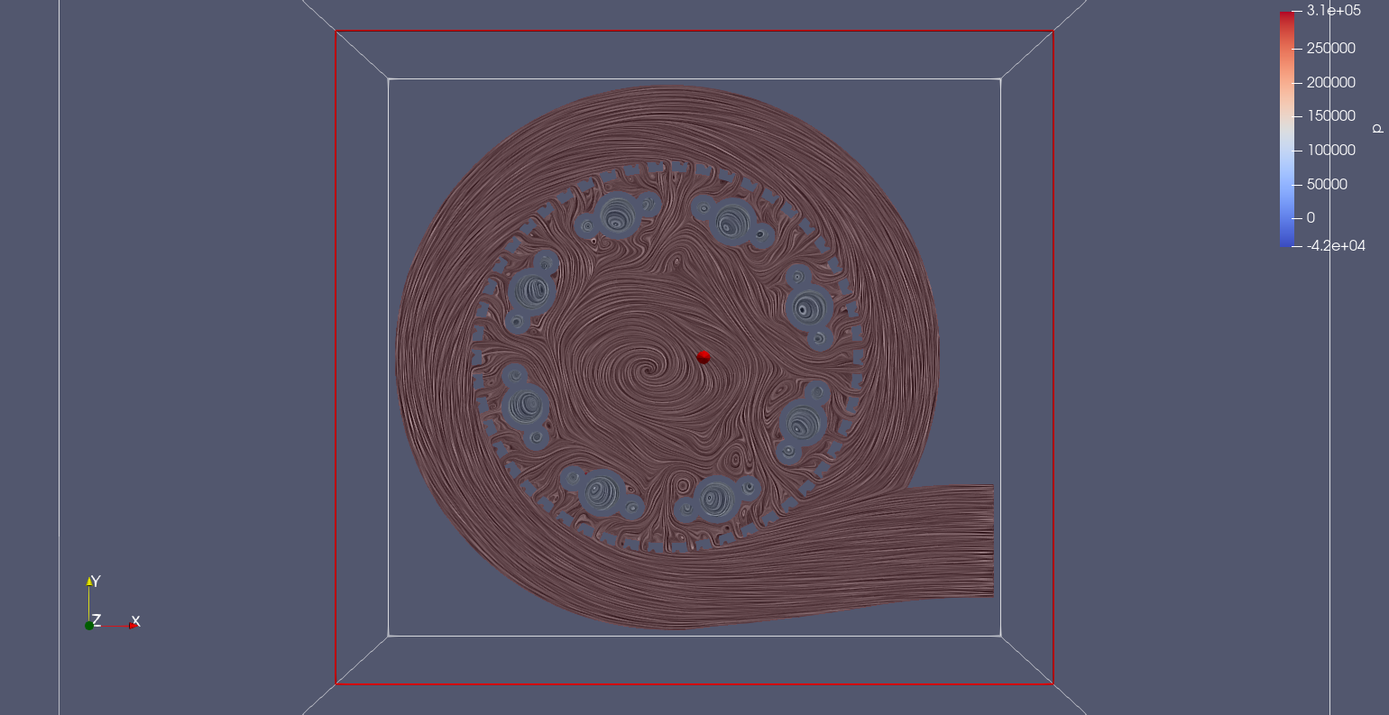
These results aren't fully converged as the pressure that the inlet was initially needed to generate a result. A pressure gradient a full vacuum, -20kPa, was difficult to set as the boundary condition. Surprise vacuums are difficult to simulate...
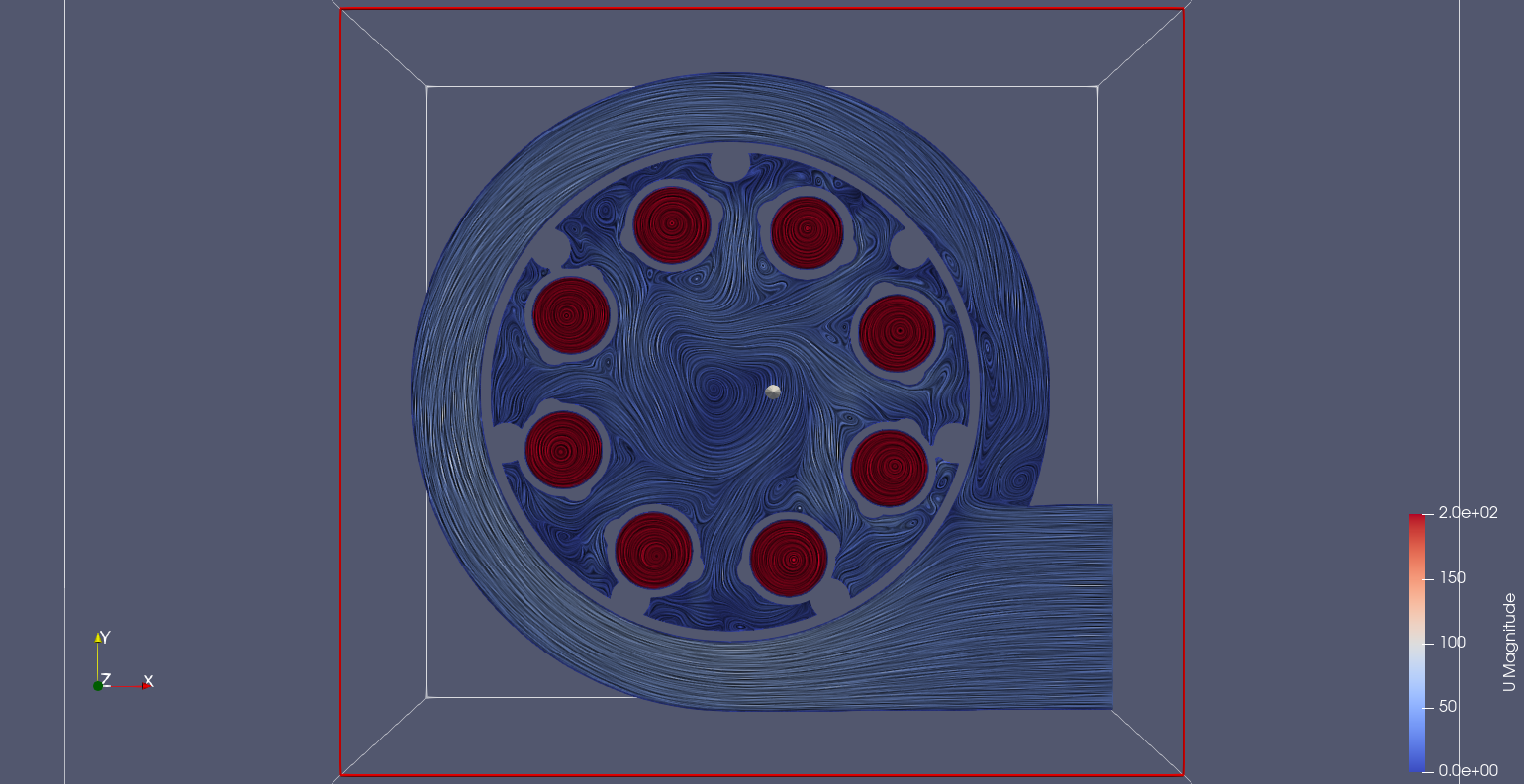
A different scale is applied from here on.
The bright red from the small cyclone generators sits just below the inner division. There is high velocity circulation inside these chambers. Doubling the scale show the lower speed of the cyclone core. Interestingly the chamber that supplys the small cyclone extractors has an amount of rotation despite passing through the outer mesh.
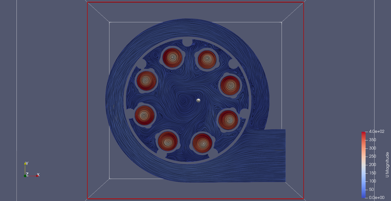
A slice taken when the small cyclone is divided between inner and outer represents the division that the extractor relies upon to separate the solid material.
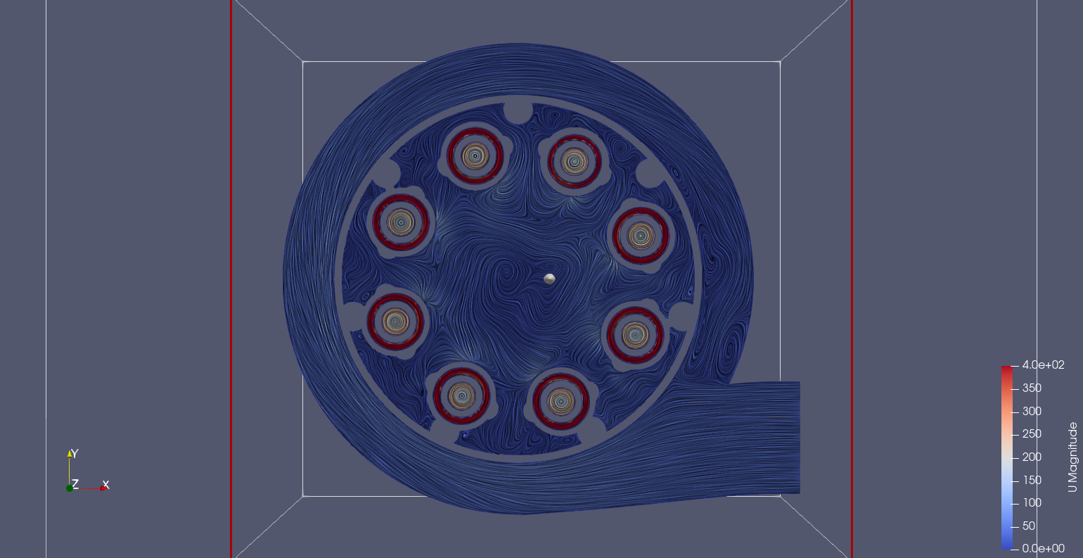
Just at the entrance to the small cyclone you can see where the air is being pulled. Obviously it comes off the mesh, but the fact it looks to come from bellow may suggest alternative geometry is possible.
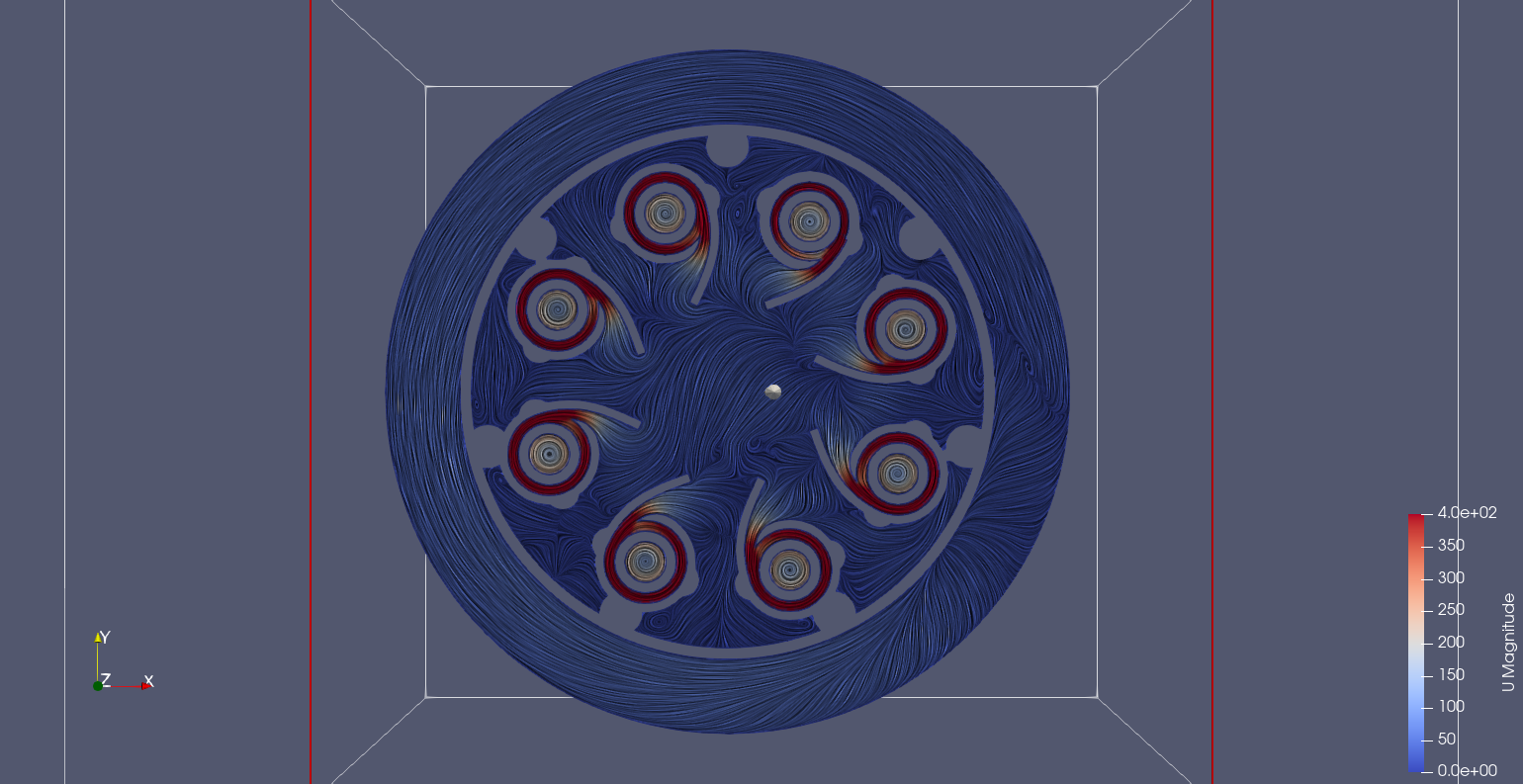
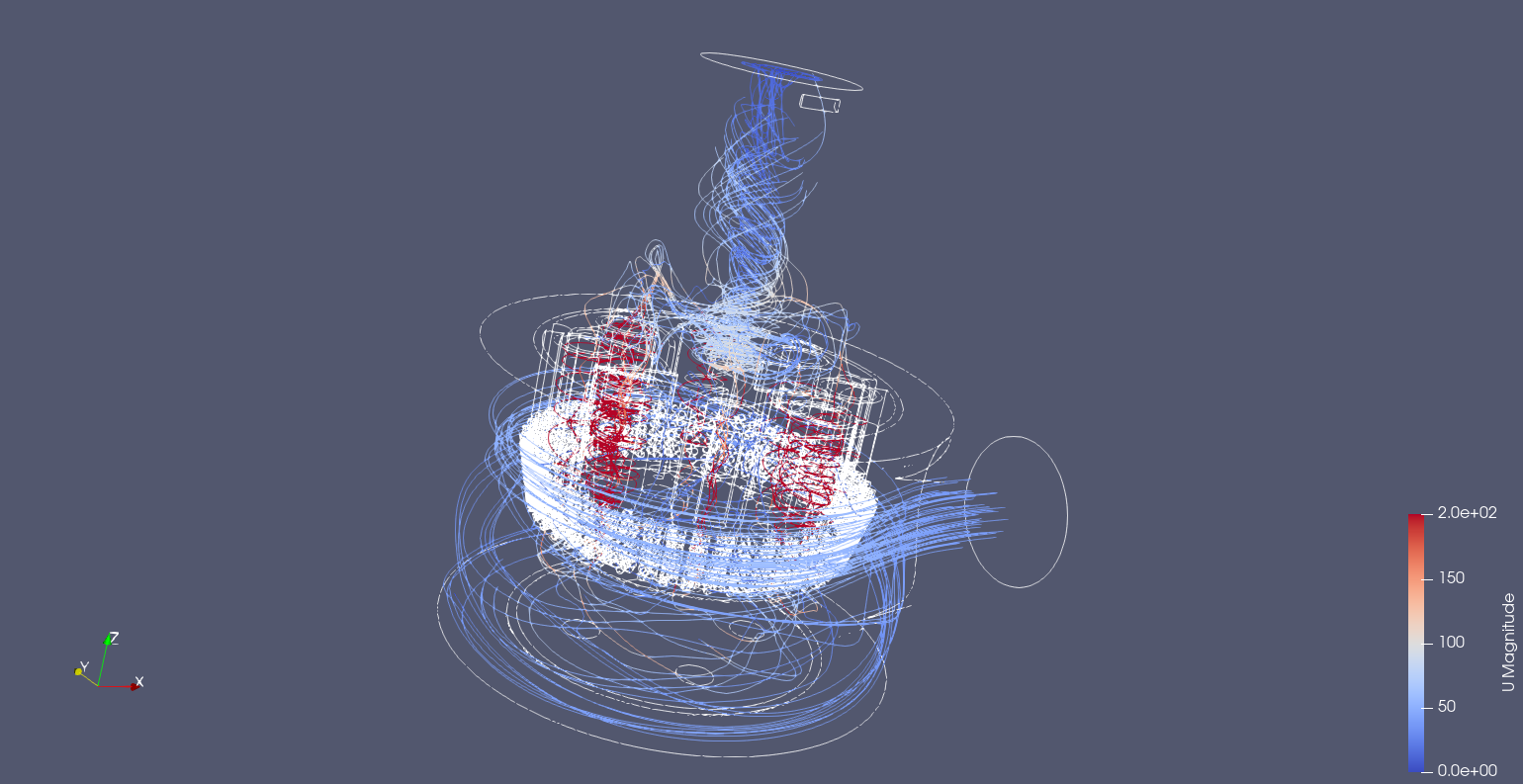
The exit funnel has a rotating column fed by the eight small cyclones, the streamlines illustrate this nicely.
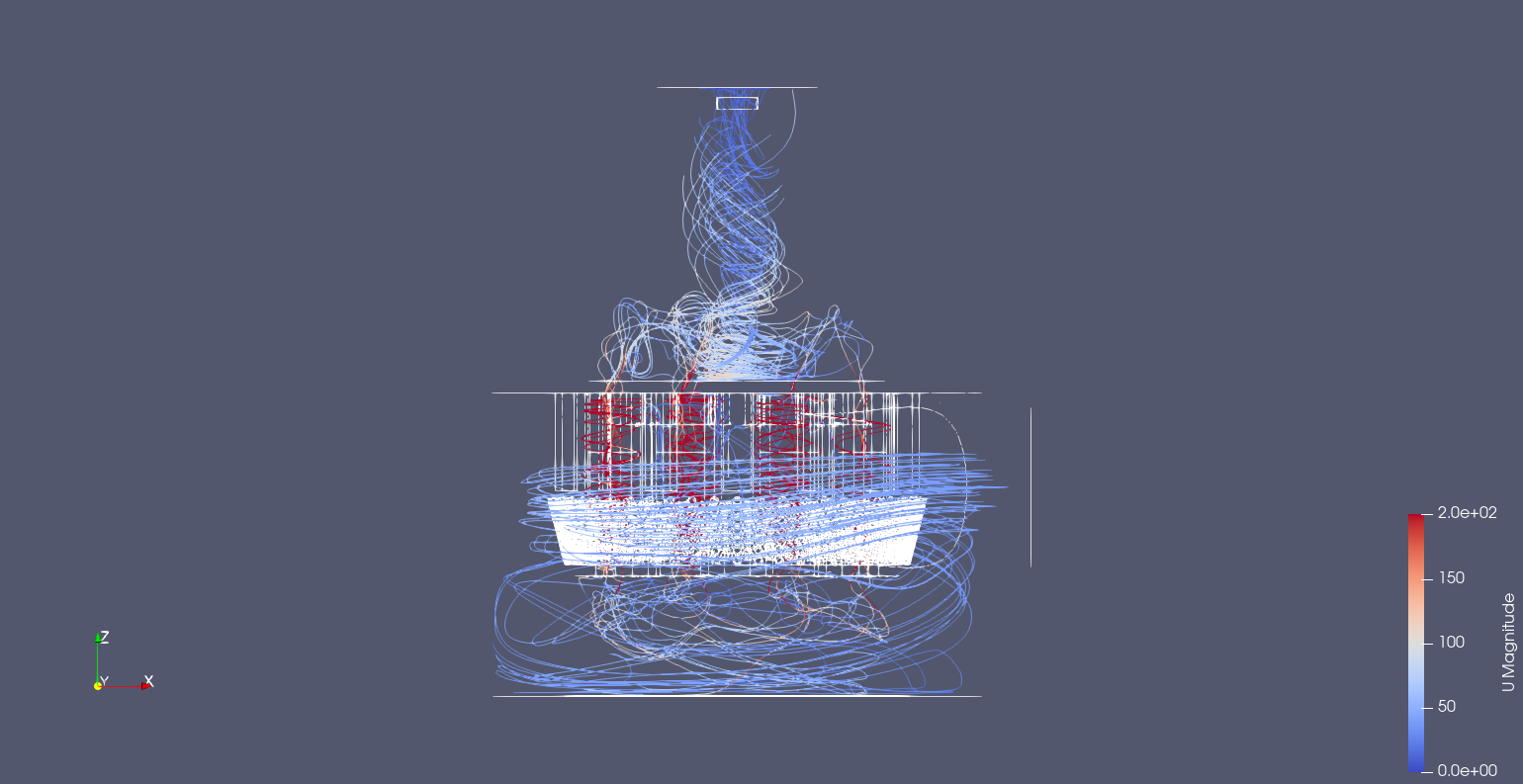
Streamlines. Note the rotating column in the outlet funnel is attached to the roof of the extractor shell. This rotating column is also fed by the small cyclones low down in the funnel.
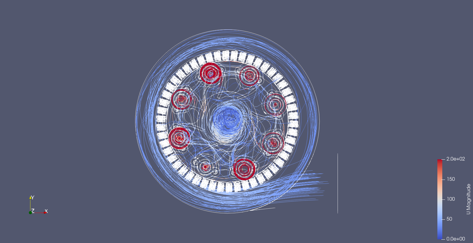
Interesting shot of how the velocity of the rotating air is slow in the middle. It would be interesting if this rotating flow structure continues far into the hose or it breaks down causing an inefficiency/blockage.
 Nelson Phillips
Discussions
Become a Hackaday.io Member
Create an account to leave a comment. Already have an account? Log In.