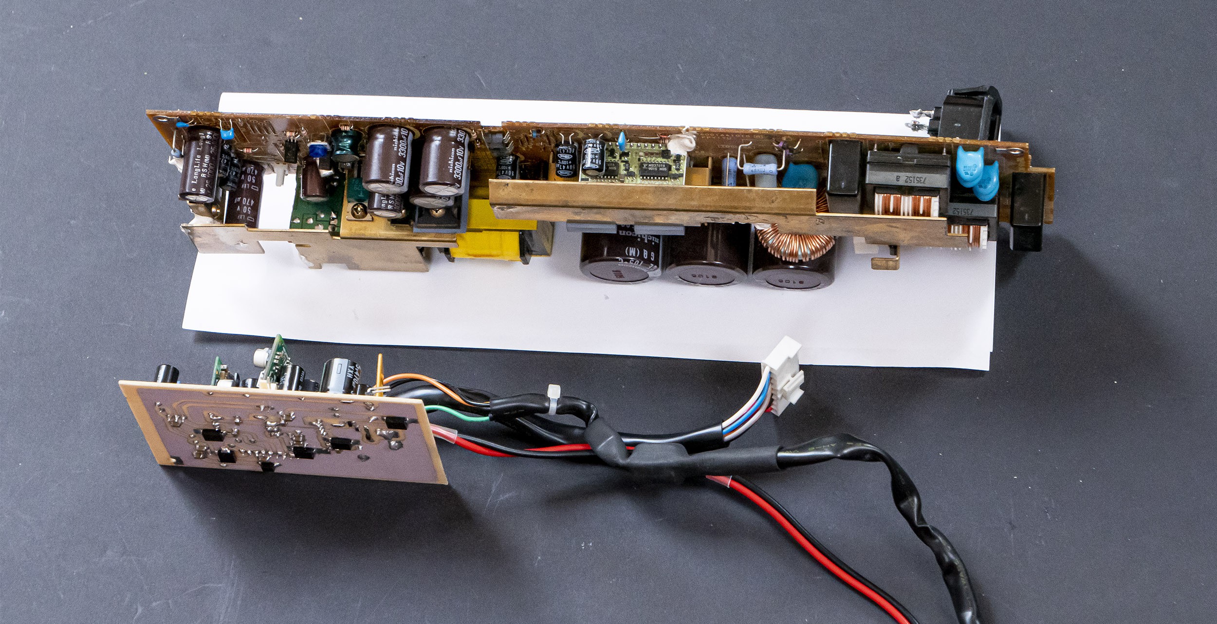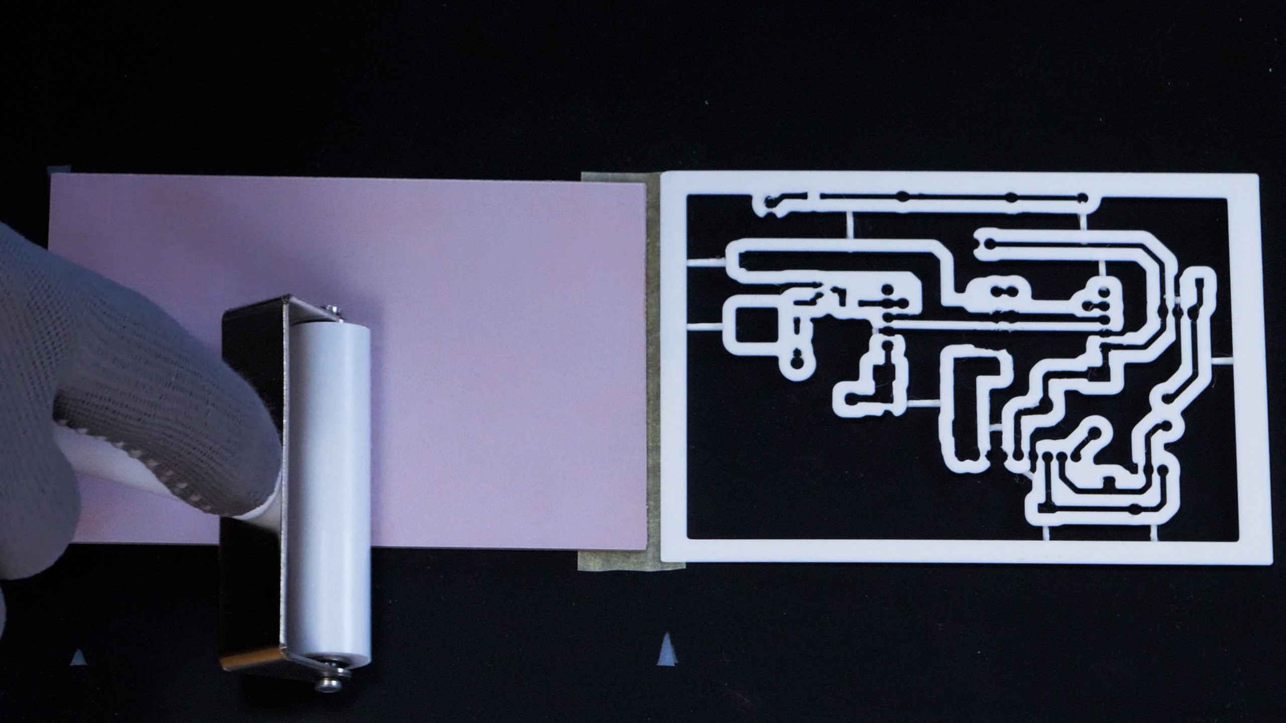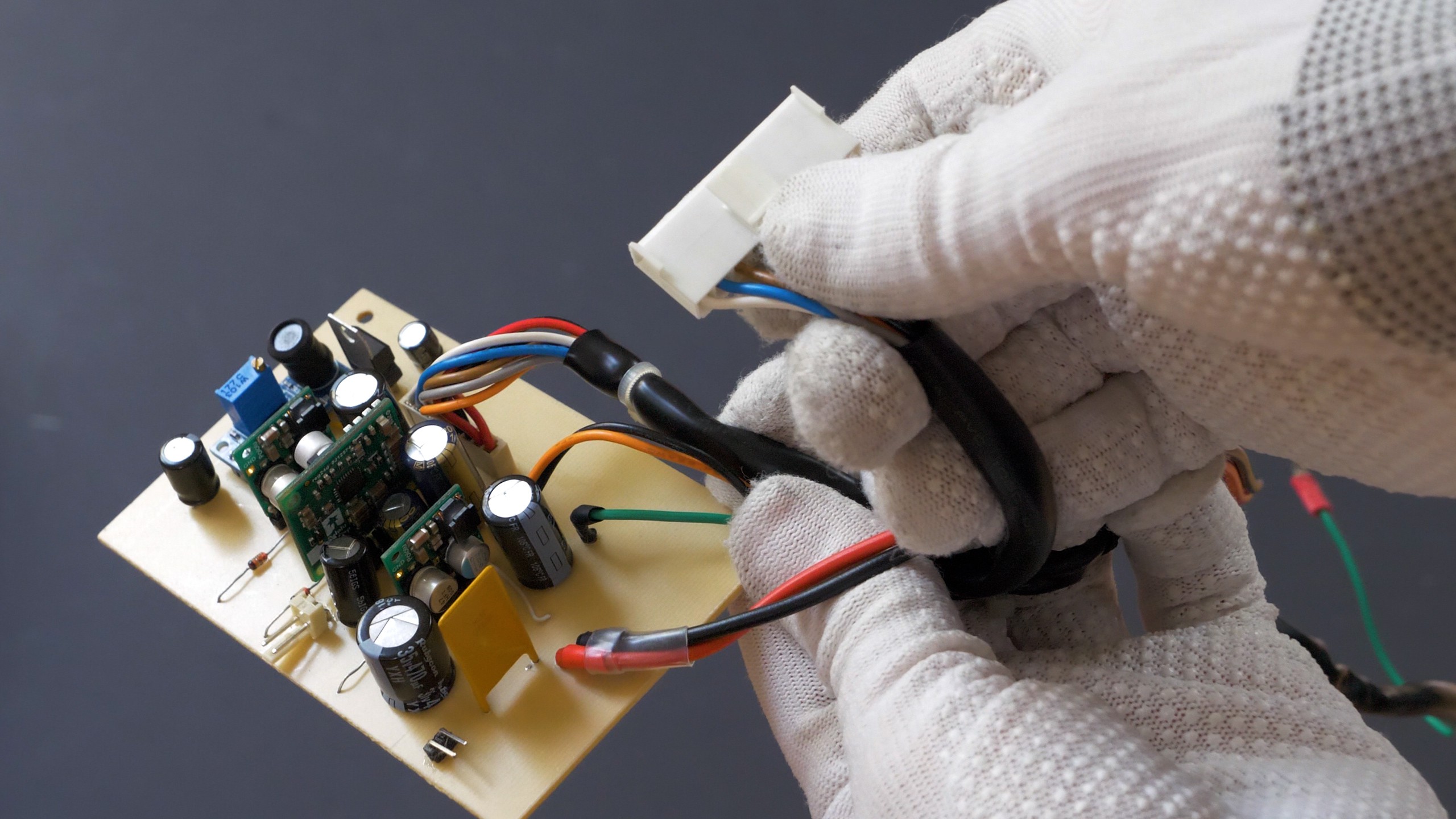
A prototype power supply was fabricated using mostly readily-available DC-DC modules and home-etched PCB made by exposing a board coated with UV-soldermask under a 3D-printed mask.
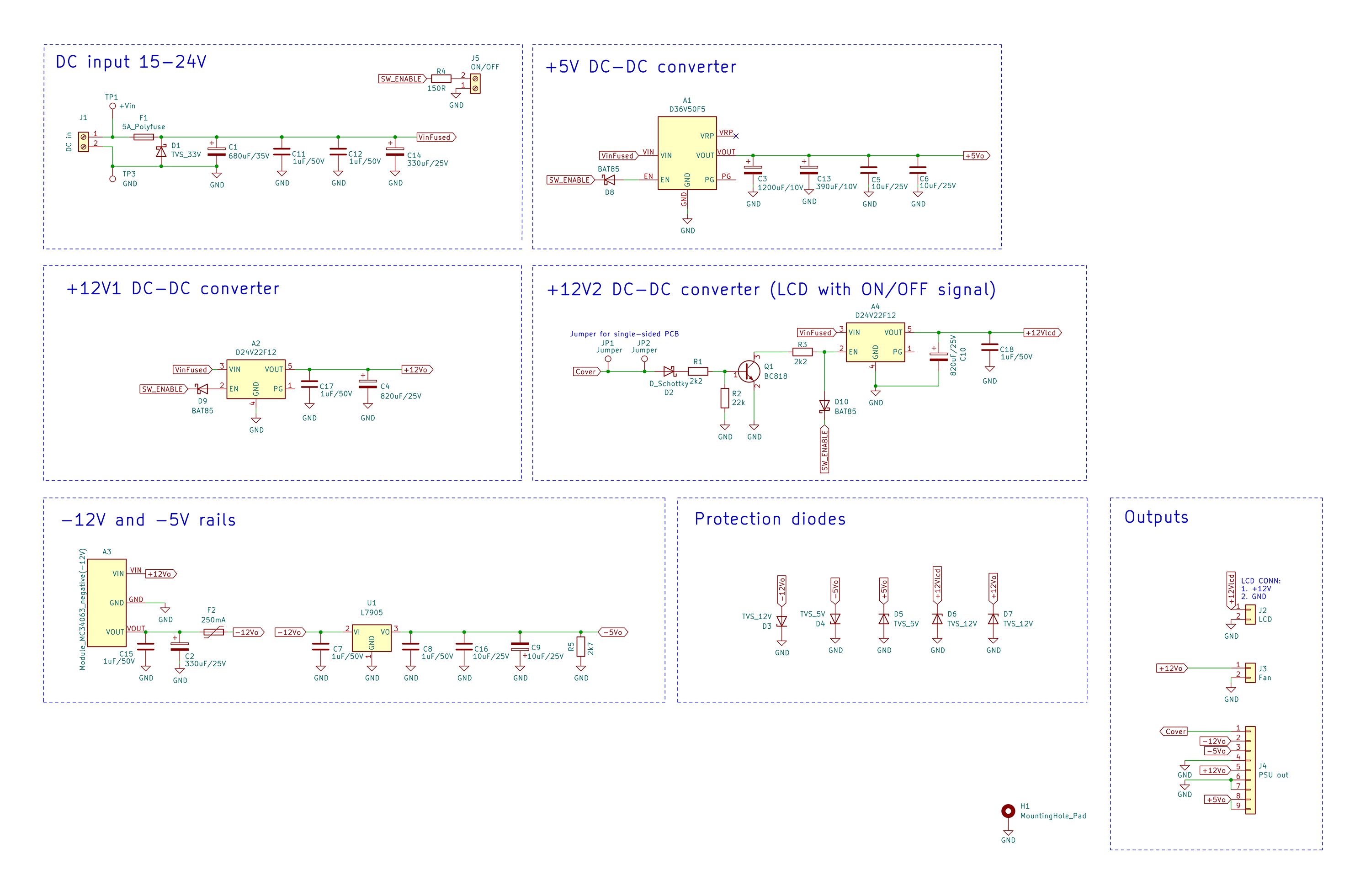
The power supply required following rails:
- +12V for mainboard/HDD
- +12V for LCD with turn on/off signal
- +5V
- -5V
- -12V


and in this video:
Major components of the power supply:
- D24V22F12 12V 2.2A step down converter x2
- D36V50F5 5V, 5.5A Step-Down converter
- LC-MC34063A-NV negative voltage converter module
- LM7905 -5V negative voltage stabilizer
- 5V and 12V SMC and SMB TVS diodes for rudimentary overvoltage protection
- 5A polyfuse
- 250mA polyfuse
- low ESR capacitors, ceramic capacitors
The power supply will be able to operate on wide input voltage range (ca. 15-24V), as all of the voltage rails are generated using step-down converters. It could be more cost effective to use just 5V and -5V, -12V converters, and use +12V directly from the DC input, but that would require some additional, active overvoltage protection, as it would be much easier to mismatch the power supply. It would be also possible to use just one +12V converter if a mosfet would be used to power the LCD on/off, but two converters were used to spread the load. ENABLE pins of +12V and +5V converters were used to provide soft power on-off functionality and to allow switching the LCD on and off (with help of additional transistor).
Discussions
Become a Hackaday.io Member
Create an account to leave a comment. Already have an account? Log In.