 John Anderson
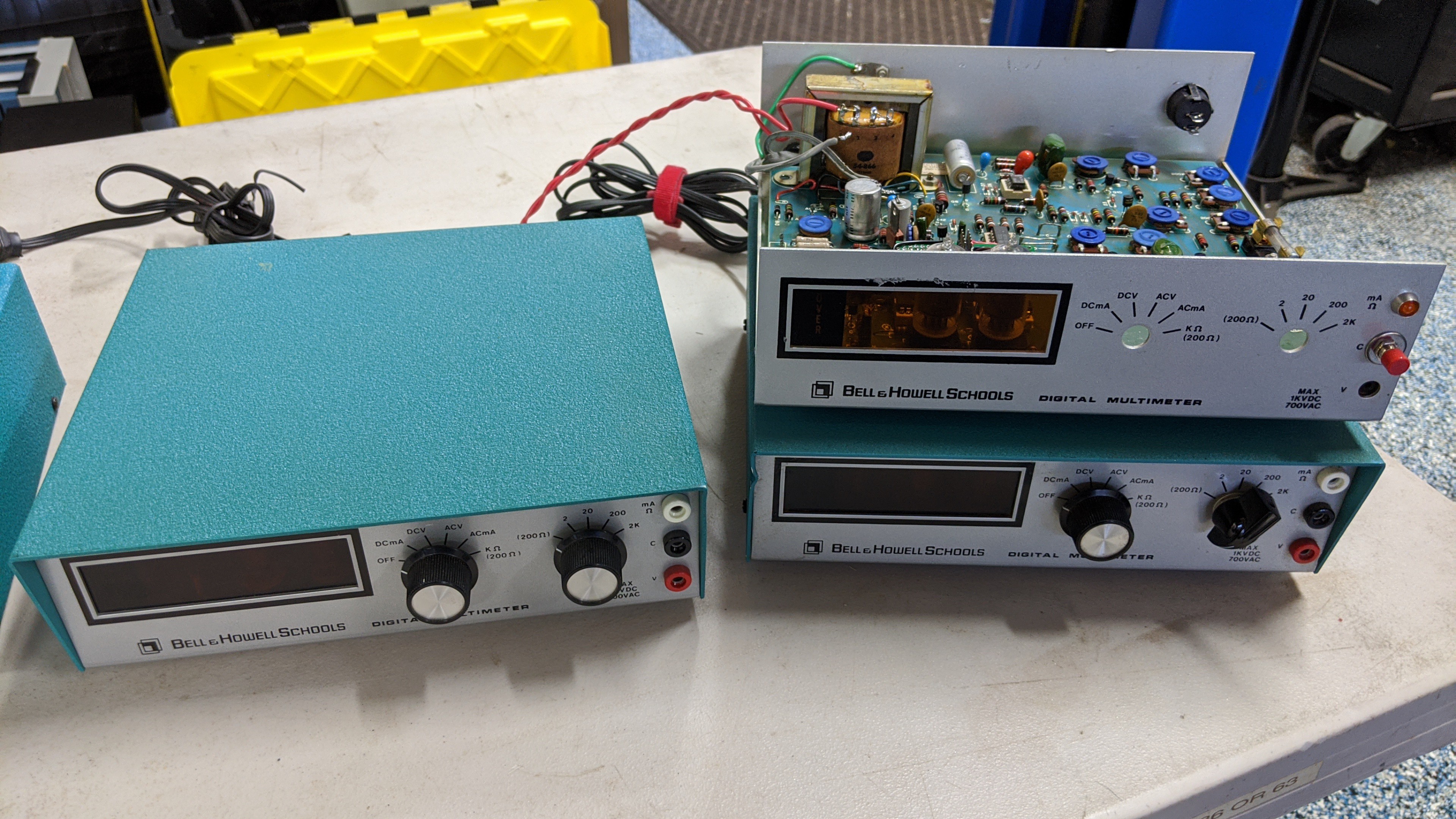
This piece "recycles" a Bell & Howell IMD-202-2 Multi-meter. These devices were part of the DeVry University electronics curriculum back in the mid-70's. If I understand it correctly, this multi-meter was a project that students built. The design is based on a Heathkit IM-1212 multi-meter. Bell & Howell apparently acquired the rights to recreate that design in a different form factor and enclosure. These multi-meters were produced in fairly large numbers. You might have one in your attic right now. Or, you can easily find functional examples on eBay. If you have a little patience, you can even buy them cheap. By cheap, I mean cheap for a project case, a couple nixie tubes, a couple 7441's to drive them, and power supply that provides the 170 volts for the tubes and the 5 volts for your custom electronics/micro-controller.
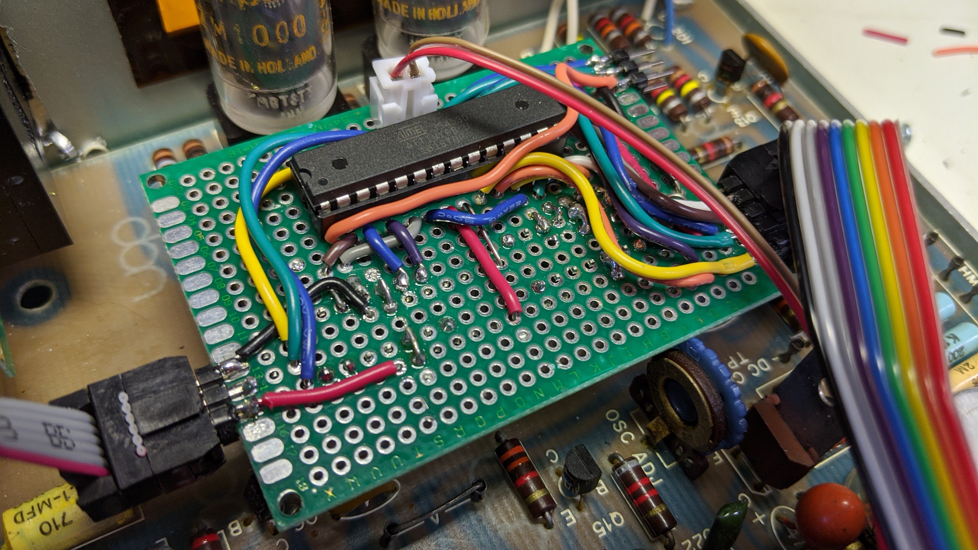
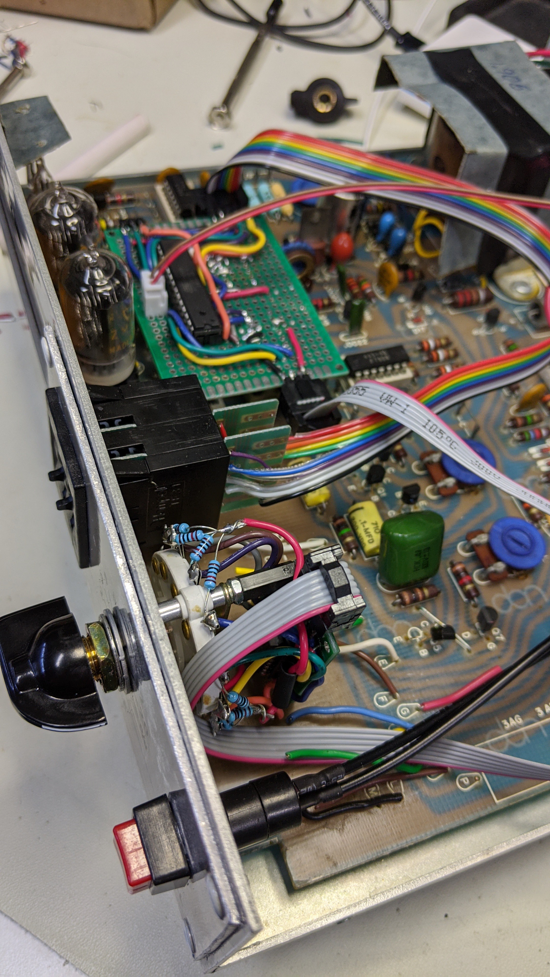
I selected a ATtiny88 AVR microcontroller for this piece. This controller is highly integrated with flash, SRAM, reset logic, integrated oscillator, etc.. I feel like I'm cheating when I use these parts. My controller board is just a 28 pin DIP socket, some wires, and 4 connectors. There is no RC circuit for the power on reset, no crystal and caps, no external bus logic, no external pull up resistors. These AVR controllers also simplify integrating with original 7400 series logic ICs. There are some limitations like the original 74xx and 74LSxx outputs can't reliably drive an AVR input logic level. But, that's not a problem for this application.
The hand built controller board with the processor is integrated with the original PCB and power supply in the Bell & Howell Multi-meter. To simplify integration, I simply removed the two DIP socketed 14 pin 74490 decade counters that are directly connected to the 7441 nixie decoder/drivers and plugged my custom board in there using a couple in-line headers.
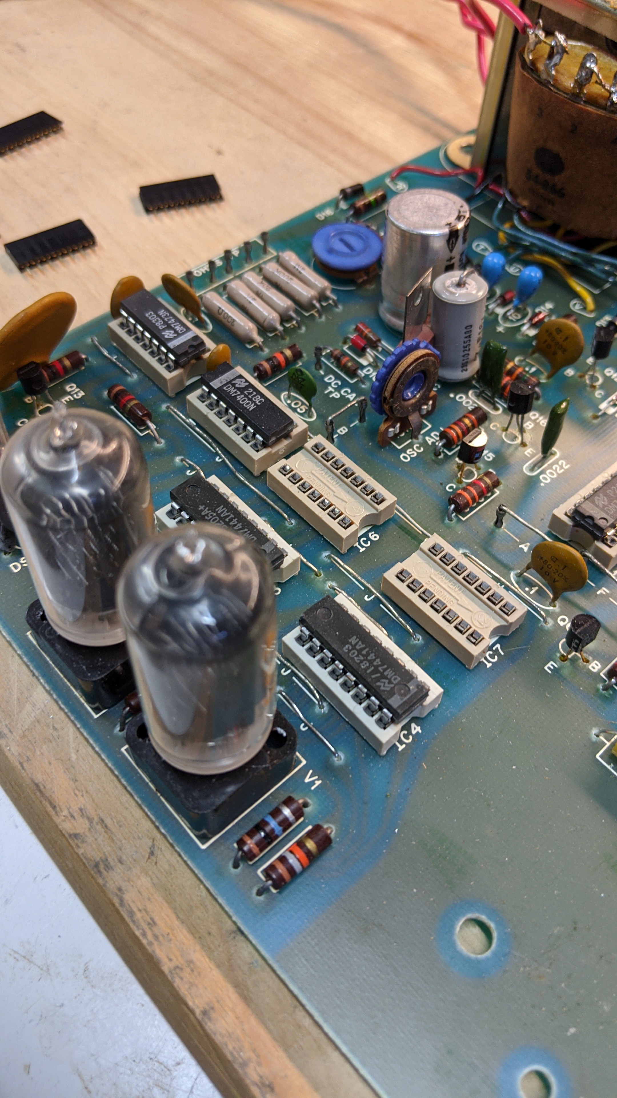
The sockets provide +5V, GND, and the two 4 bit BCD interfaces needed to power the controller board and drive the display.
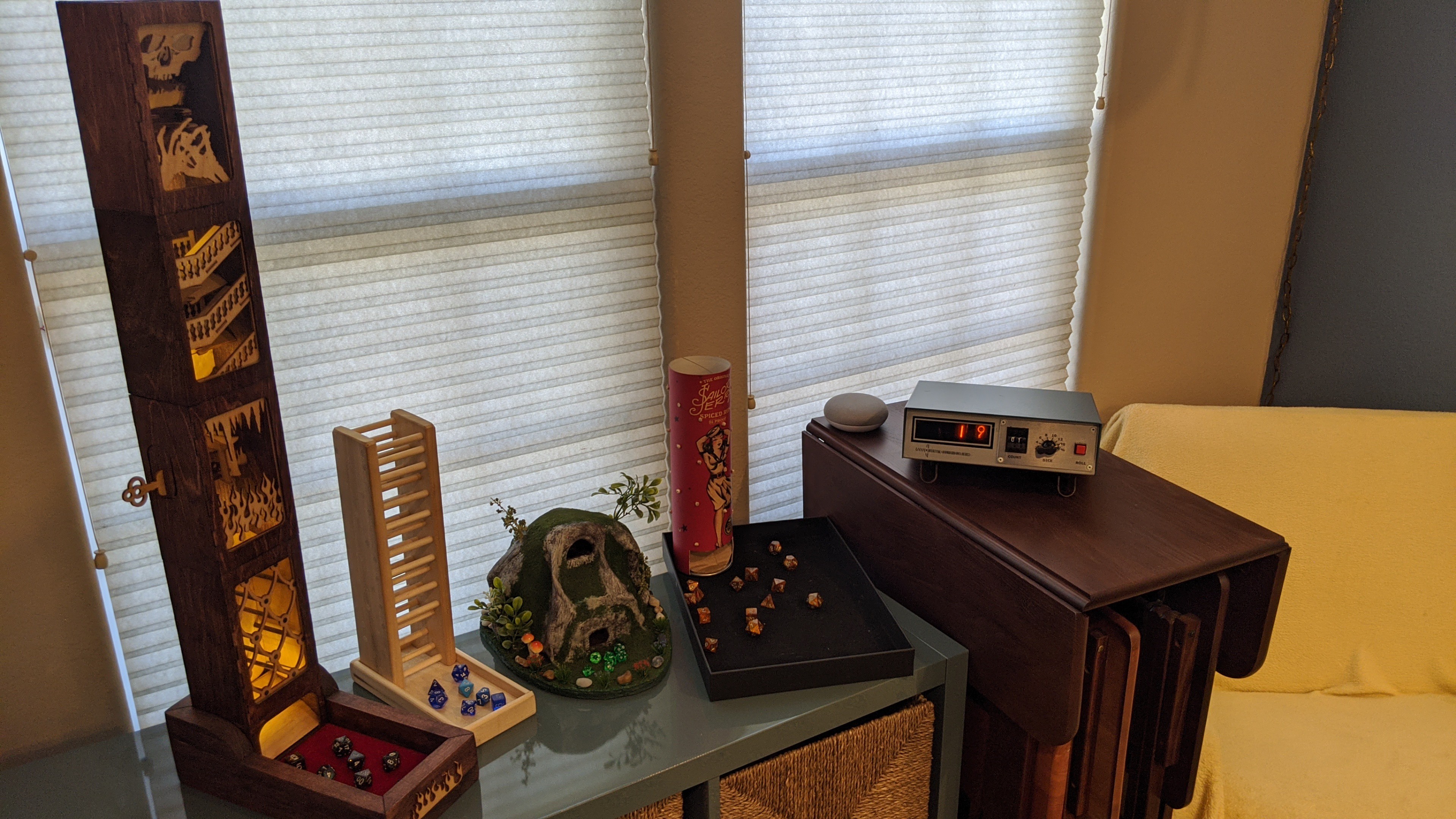
The rest was just a matter of removing the old switches and banana plugs, riveting in a new face plate, installing new switches, connecting them to the controller board, writing some simple code, and applying new graphics. In this case, I used a 8-way rotary switch for the dice type select, a two digit thumbwheel switch to select the number of dice to be rolled, and a square panel mount push button to roll the dice. Software was developed from scratch using the freely available Atmel Studio 7.0 IDE and toolchain. And, the new graphics were printed on water slide decal paper and transferred to the new face plate.
The resulting piece looks and works like this.
Discussions
Become a Hackaday.io Member
Create an account to leave a comment. Already have an account? Log In.