 John Anderson
To build the Bell & Howell digital multimeter based digital dice tower, you first need to get a Bell & Howell IMD 202-2 Digital Multimeter. These were originally kits that were assembled as part of the Bell & Howell electronics curriculum back in the late 70's. Apparently, the course and/or the kits were reasonably popular at the time. Because, it's not hard to find them in decent condition today.
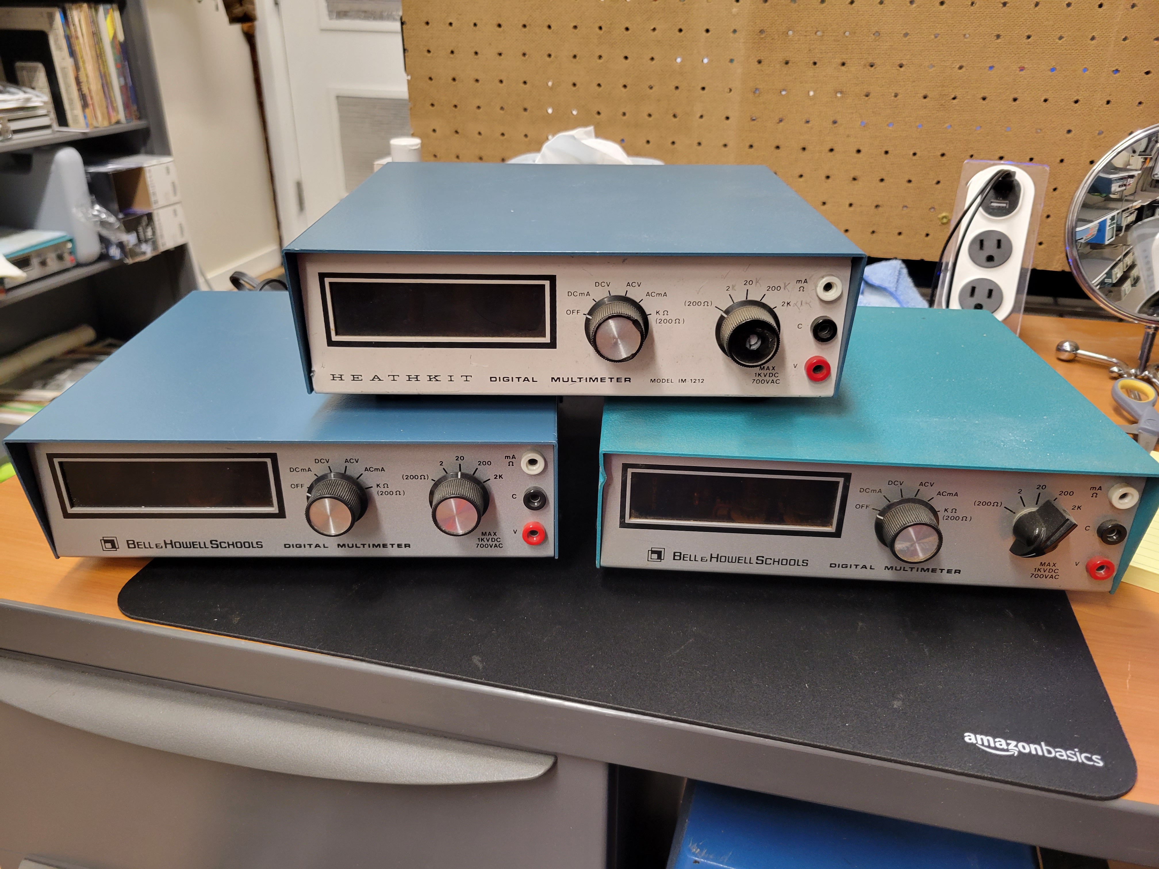
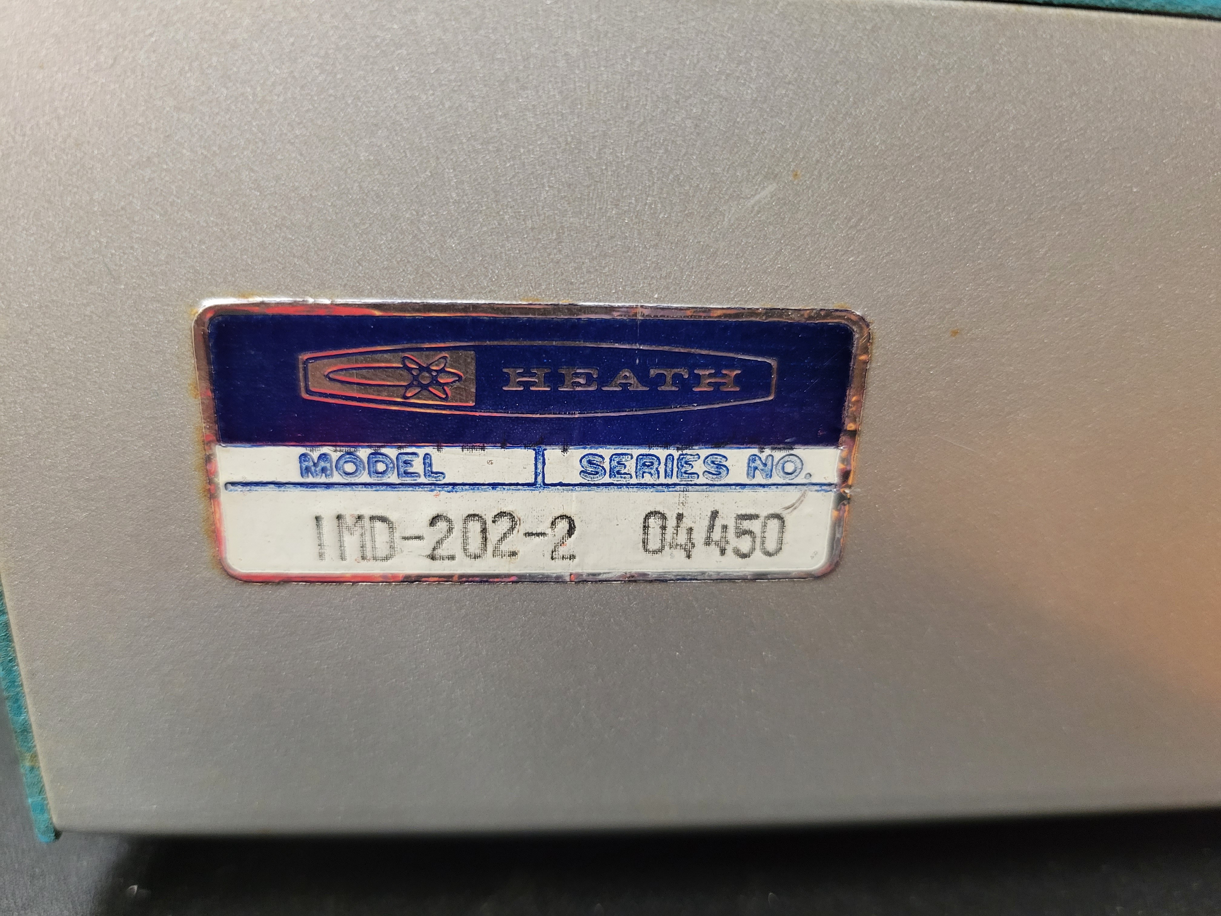
Note: In the picture above, I've included a Heathkit model IM-1212 digital multimeter as well. That is the original design the Bell & Howell IMD-202-2 is based on. So it can be a substitute for the Bell & Howell meter. However, the Heathkit IM-1212 are a little harder to find and tend to cost much more.
As you can see in the picture, they came with one of two different paint schemes for the top of the case. The internals are all the same no mater which case top it has.
I bought all of my meters from Ebay. If you have a little patience, you can buy one in pretty good condition for $50 plus shipping. That's a pretty good deal for a case, nixie tubes, 7441 decoder/drivers, power supply, and power cord.
Tip: Don't buy one of these meters unless the seller has a picture of it powered up and the Nixies are displaying readable digits. The only bad component I have discovered in the 15 different meters I have bought, is one or two bad 7441 decoders/drivers. These are not easy to find or cheap to replace. If they are bad, you won't be able to display digits on the nixies. So, make sure the seller posts a pic of it powered on with the digits displaying.
The remainder of the parts can be purchased new from various sources like Amazon or Digi-key. Although buyer beware when ordering parts from Amazon.
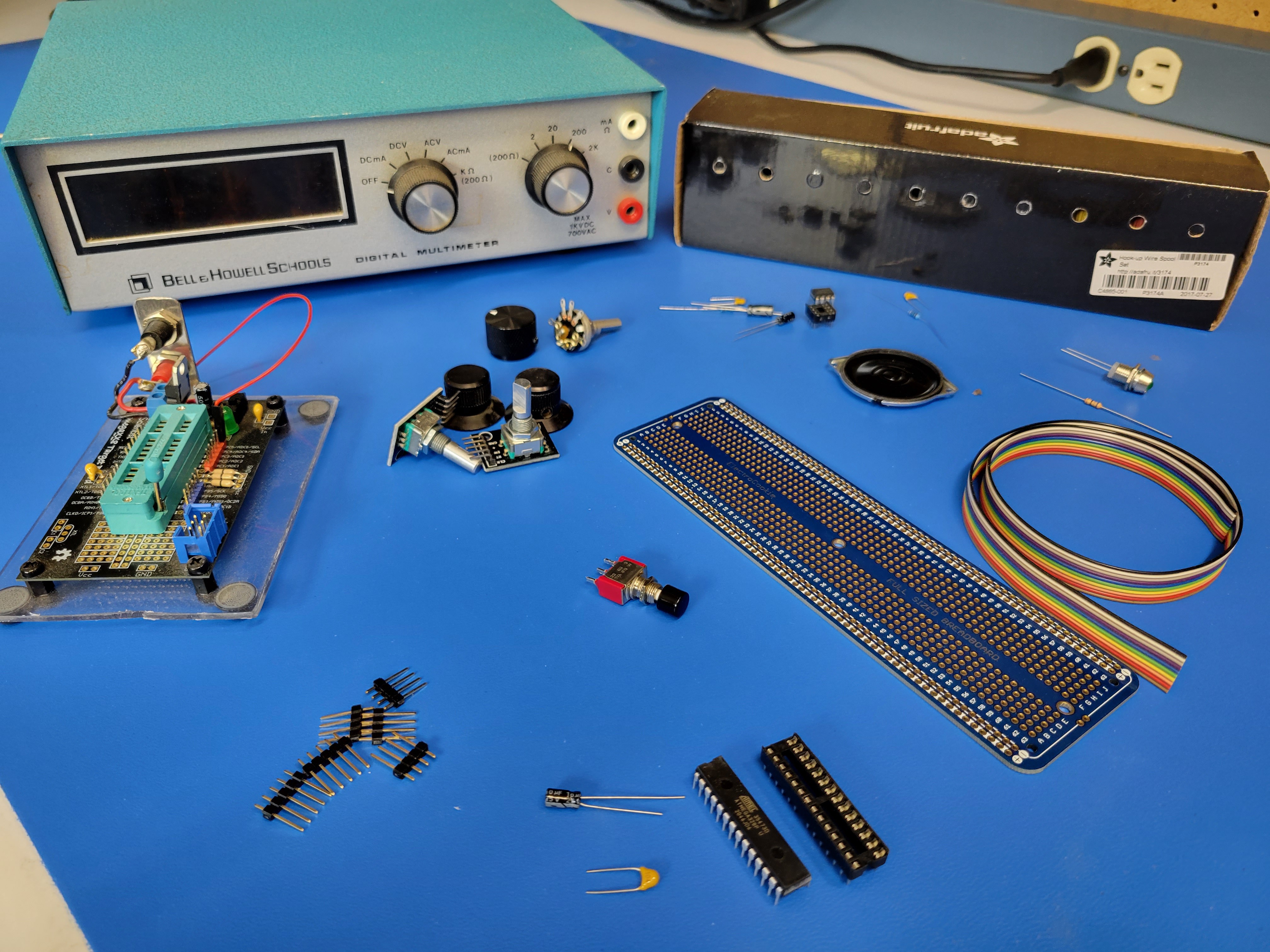
Here's the Bill of Materials (BOM) for all the components.
Audio
- LM386-1 op amp in 8 pin dip package
- 8 pin dip socket
- 10 potentiometer
- 10 Ohm resistor
- 0.1 uF ceramic cap (104)
- 10 uF electrolytic cap
- 220 uF electrolytic cap
- small 8 Ohm speaker
Audio low pass filter
- 0.1 uF ceramic cap (104)
- 200 Ohm resistor
Decoupling capacitors
- 10 uF electrolytic cap
- 0.1 uF ceramic cap
Microcontroller
- ATmega 328P in 28 pin dip package
- 28 pin dip socket
Controls/Indicators
- 6mm Panel mount momentary push button switch
- 2 pcs KY-040 Rotary Encoder Module
- 5mm LED (Green)
- 68 Ohm resistor
- Panel mount 5mm LED holder
- Small panel mount 10K potentiometer
Misc
- On/Off toggle switch at least 120V/2A
- 10 conductor ribbon cable
- Single row 2.54mm header (40 pins)
- Spool or two of 22 awg solid core wire (I like Adafruit's Hook-up Wire Spool Set)
- 63 Row solderable breadboard (I use ElectroCookie's Large Solderable Breadboard)
- Evil Mad Scientist ATmegaXX8 Mini Dev Kit (https://shop.evilmadscientist.com/tinykitlist/230)
Discussions
Become a Hackaday.io Member
Create an account to leave a comment. Already have an account? Log In.