 John Anderson
Next we'll connect the volume potentiometer, rotary encoders, button, LED, and speaker to the controller board.
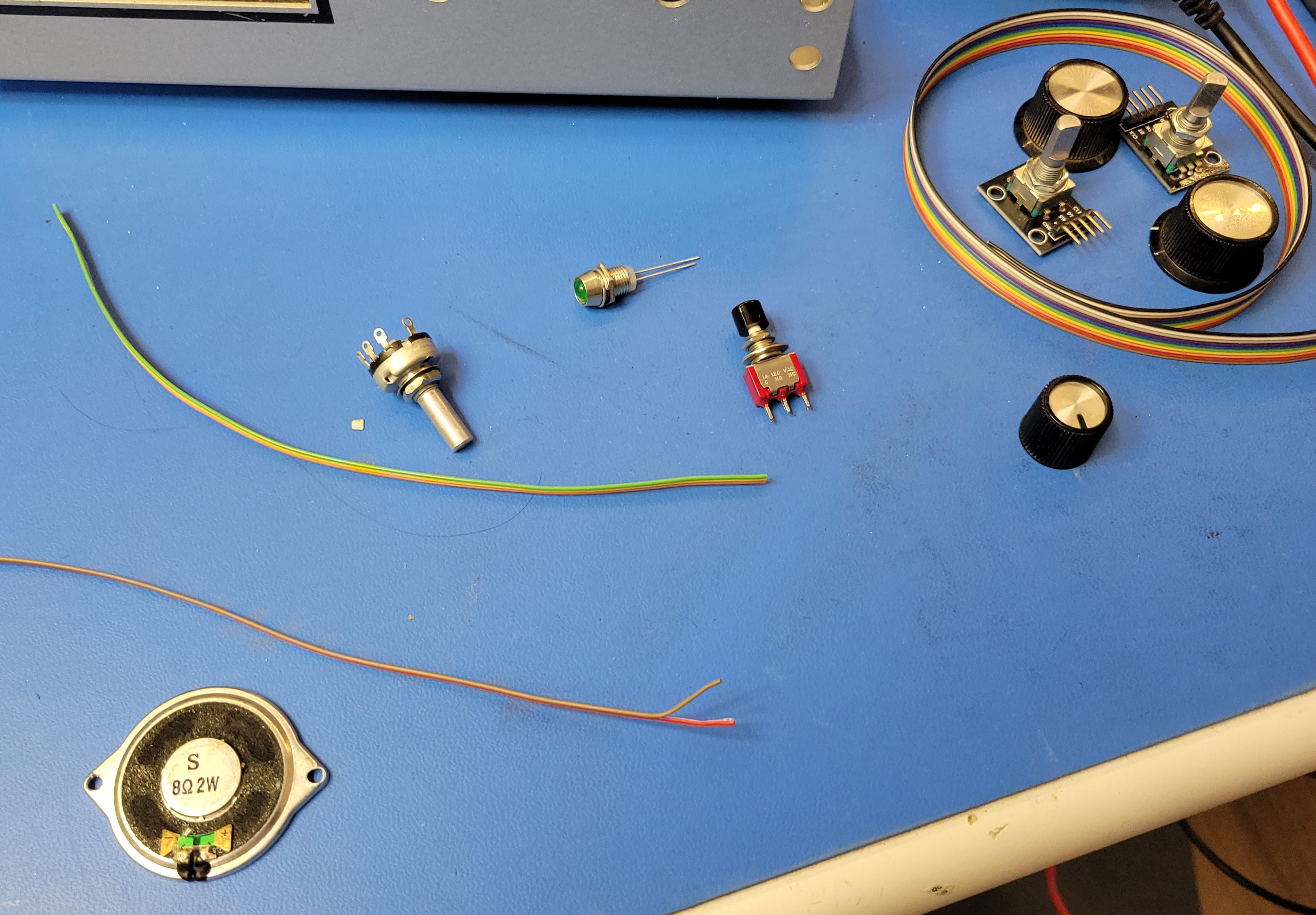
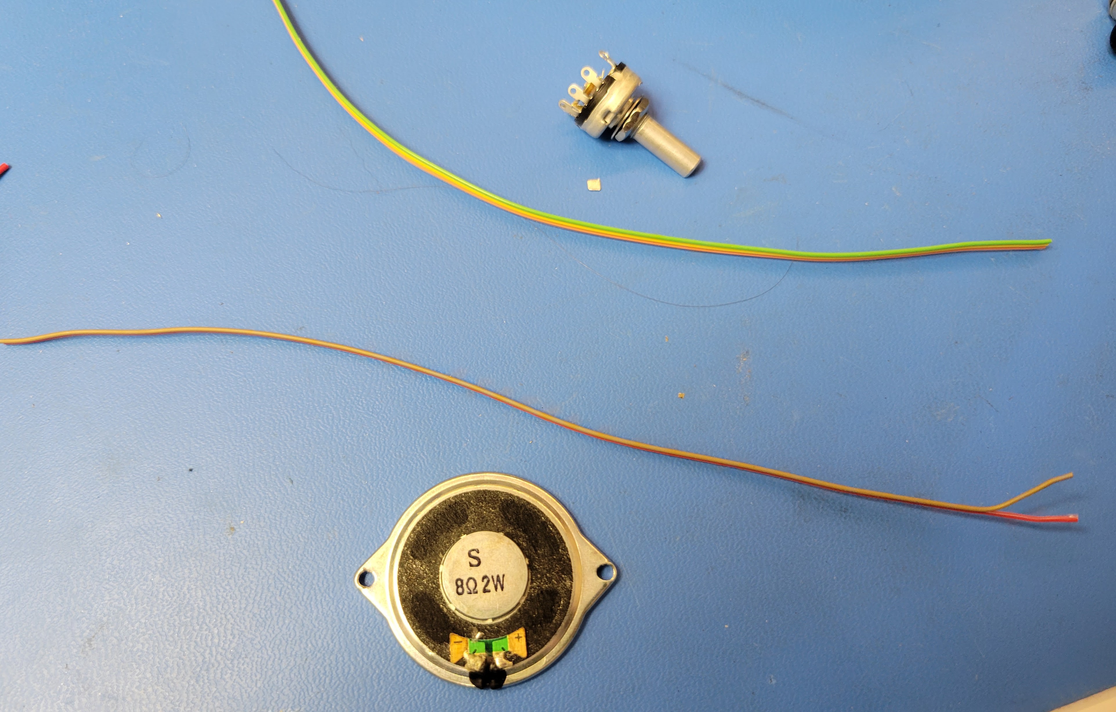
Start with an 0hm speaker and a small 10K potentiometer with appropriate lengths of 28 awg stranded ribbon cable wire. You'll need two conductors for the speaker and 3 conductors for the volume potentiometer. I have a stash of 10 conductor ribbon cable I pull these from and cut to approximately 8" to 9" length.
First, solder the tow conductor wire to the speaker.
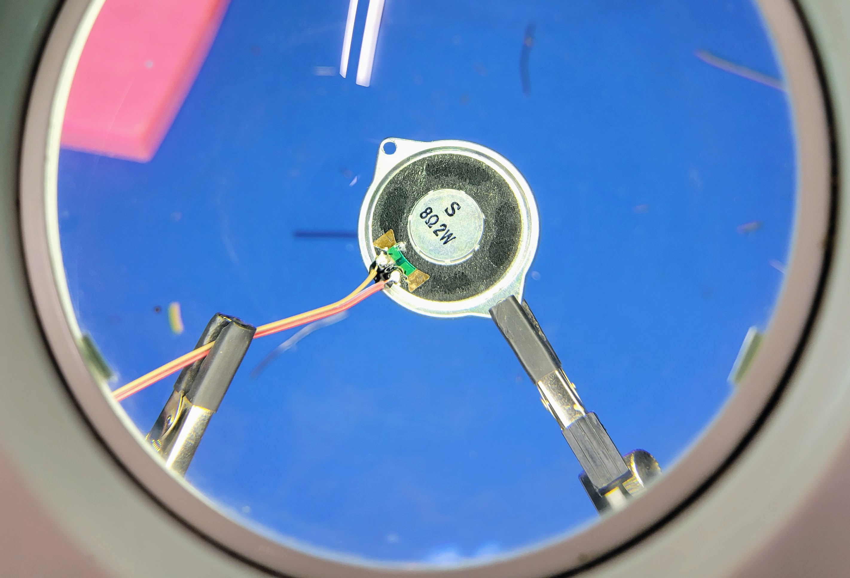
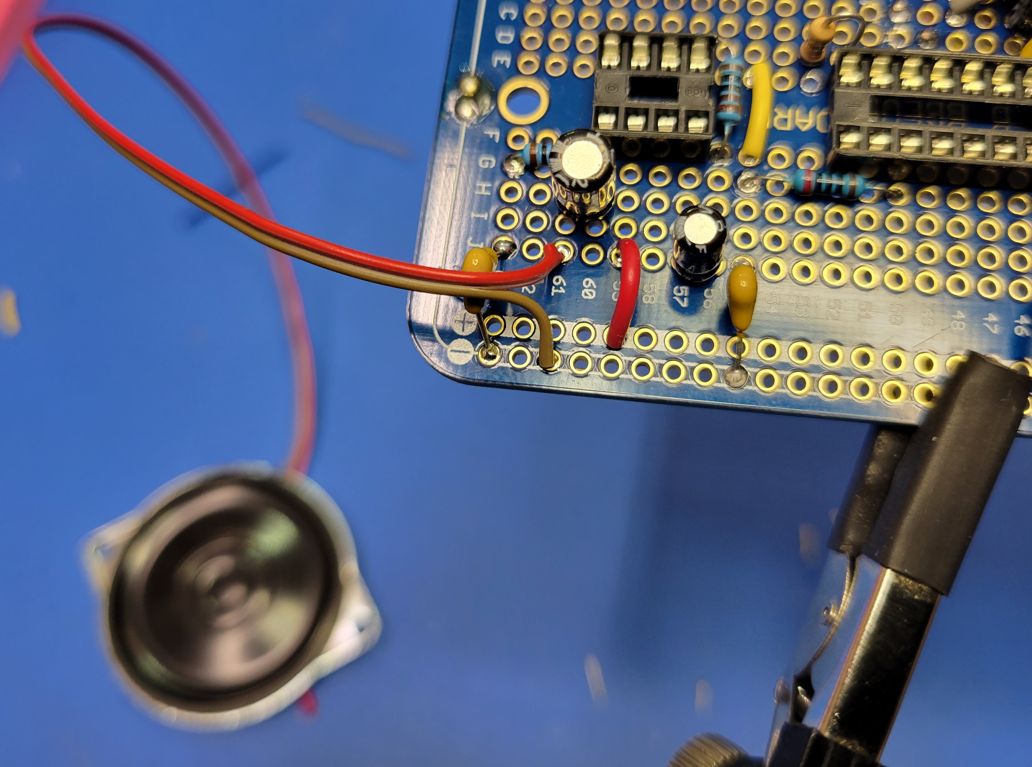
Then solder the other end of the speaker wire + to row 62 column J. This is the negative side of the 220 uF filtering cap.
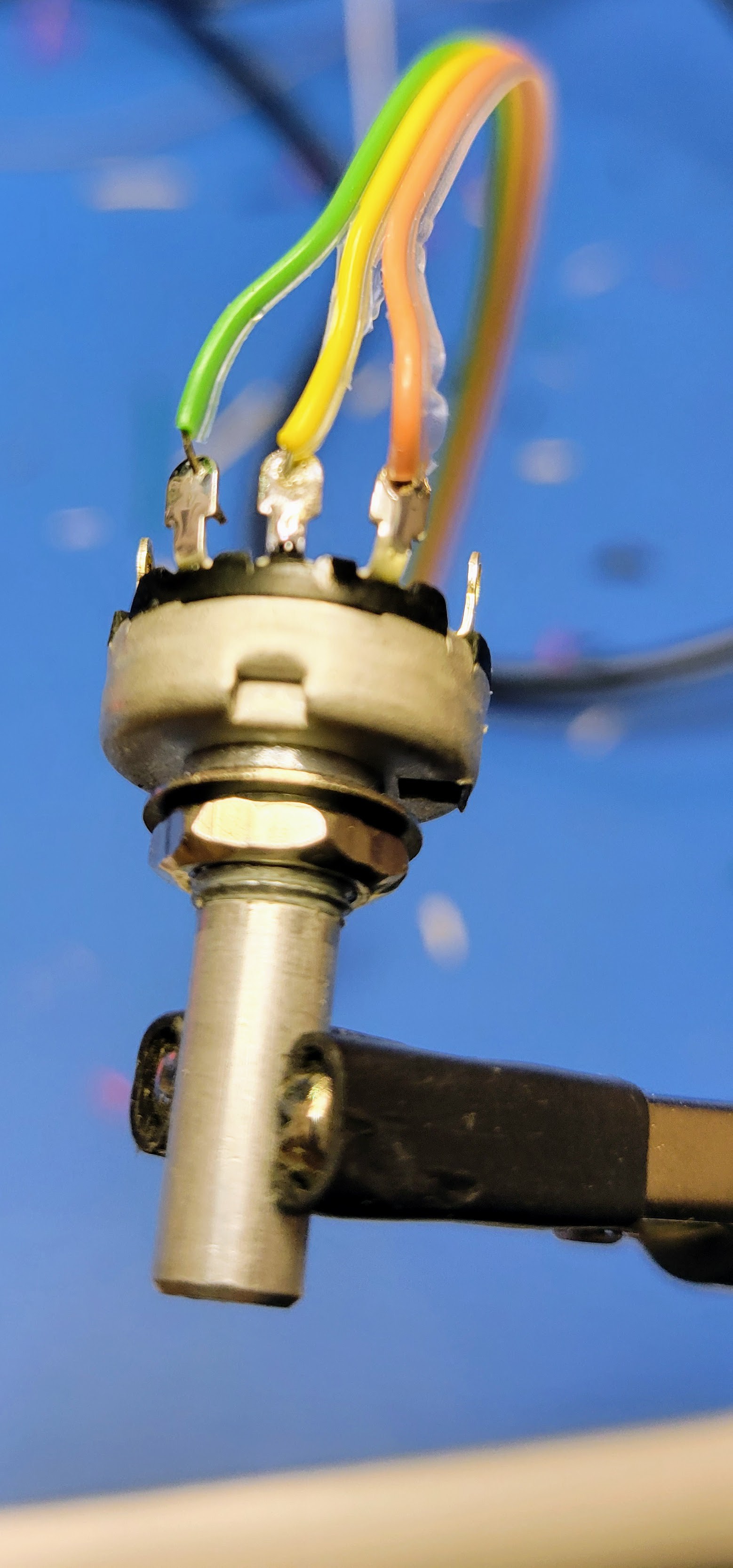
Next solder the three conductor wire to the small (5/8" diameter) 10K potentiometer. Before doing so, confirm which of the leads should be wired to signal input should be wired to ground.
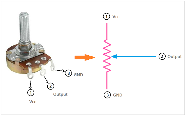
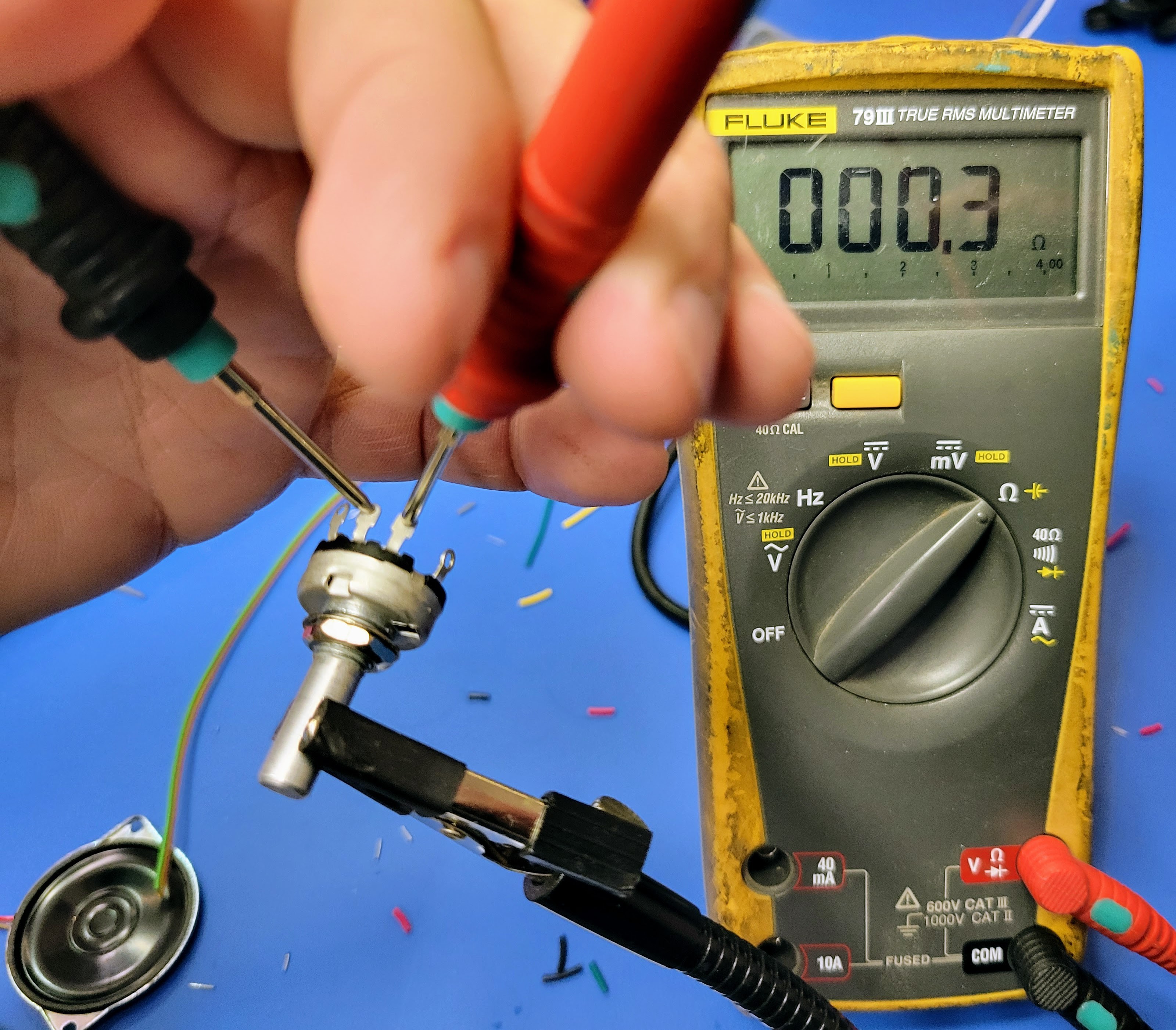
The center lead/lug is the wiper and that will be wired to signal output to the audio amplifier. Turn the shaft all the way to the left (turn the volume down). Then check the resistance between the center lug and each of the other two lugs. Ground will be connected to the lug with near zero resistance and the input will be connect to the lug with near 10K resistance.
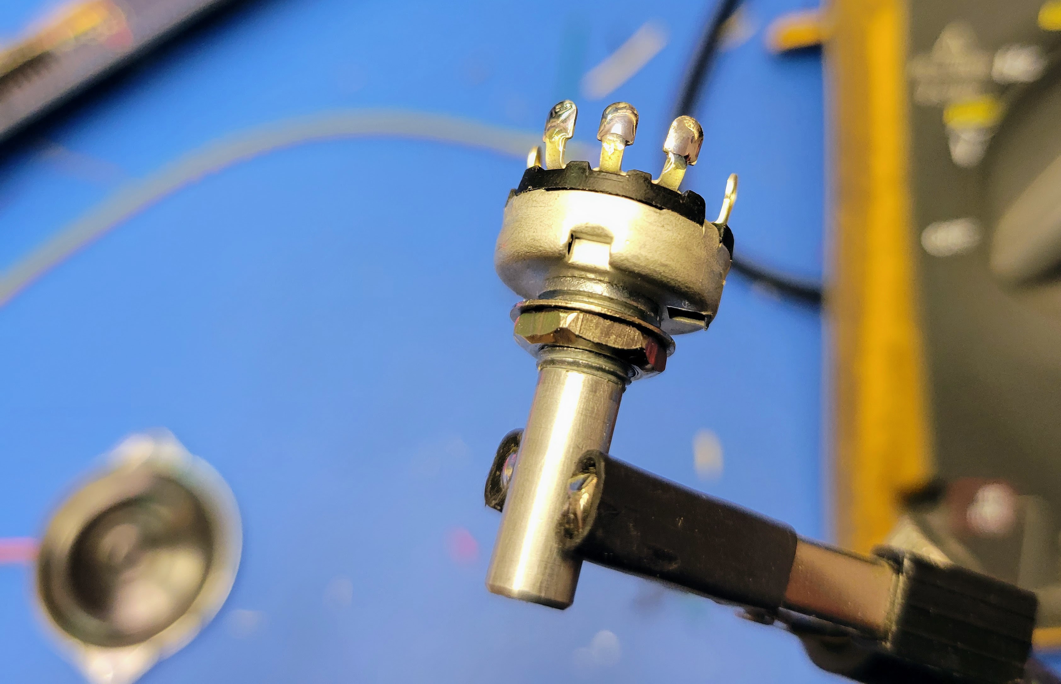
For solder lugs like the ones I have here, it's easiest to blob some solder on the lugs before connecting the wires.
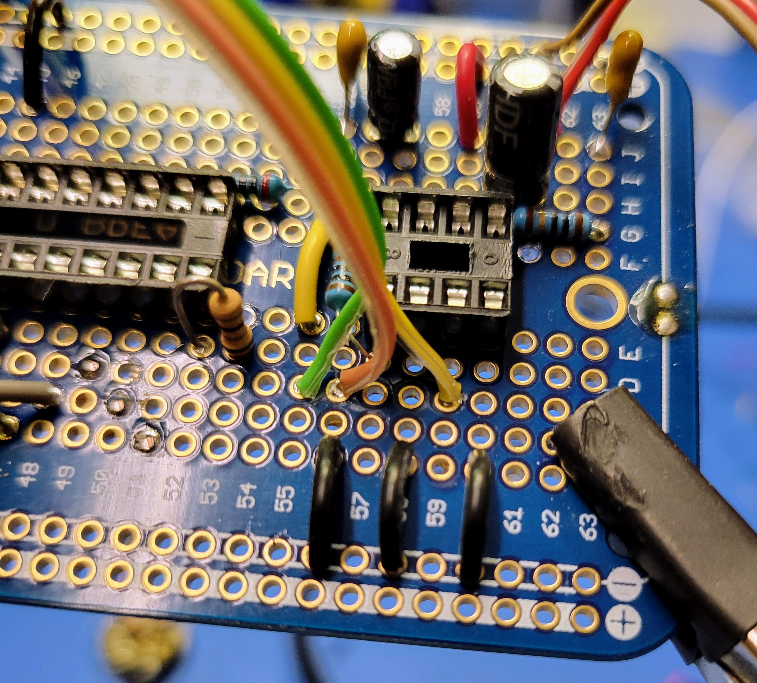
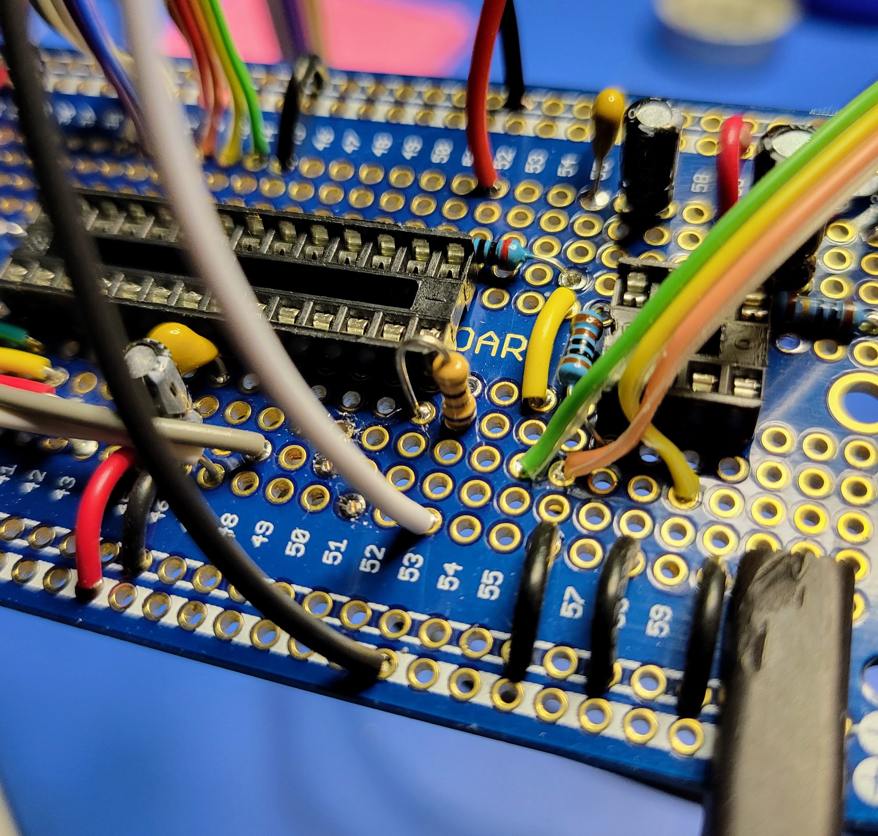
The wires from the potentiometer are then connected to the controller board.
- The ground lead wire is connected to the ground bus
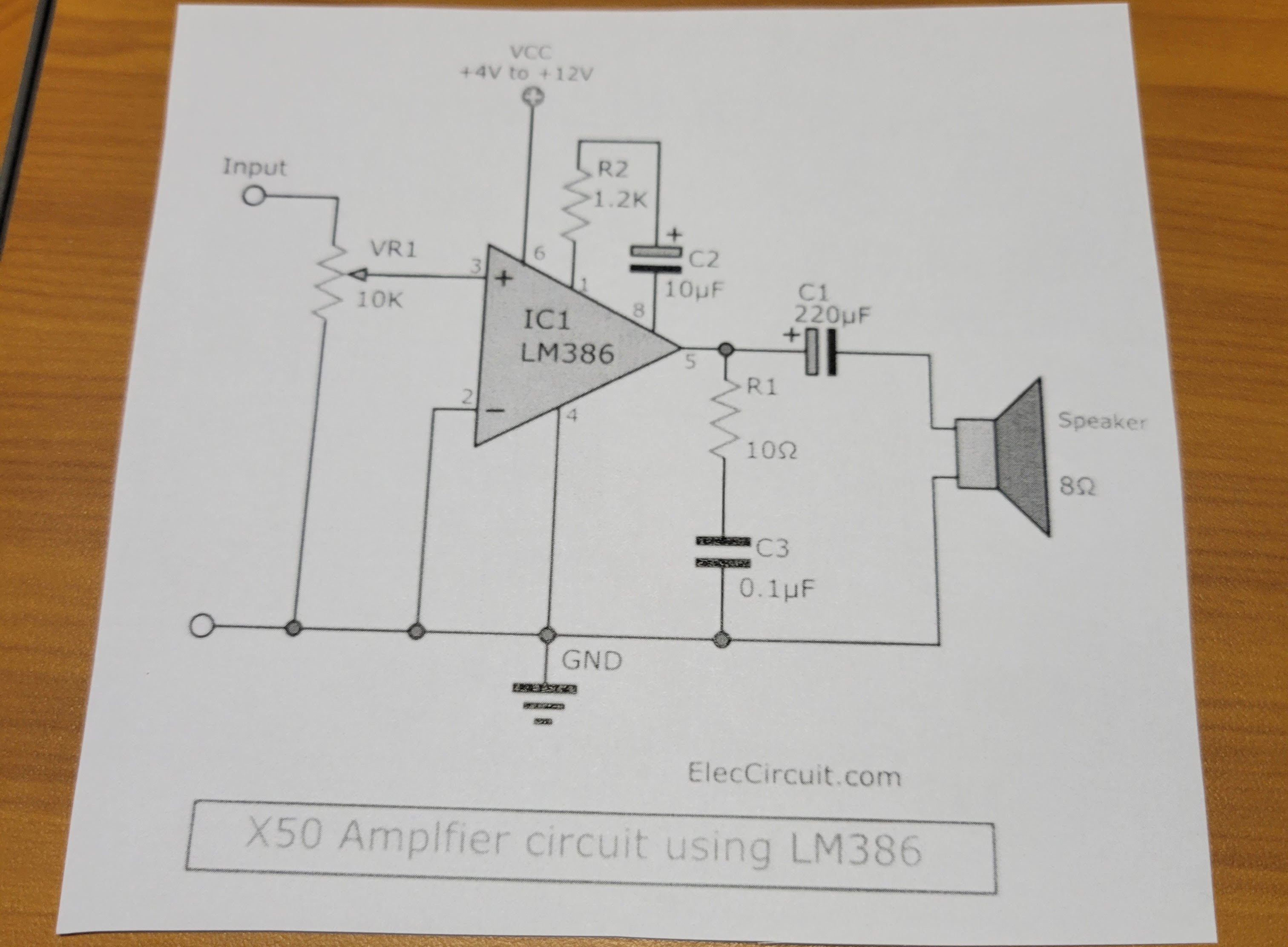
- The input signal lead is connected to the output from the RC filter connected to pin 17 of the microcontroller (row 55 column C)
- The output signal is connected to pin 3 of the audio amplifier (Row 59 Column C)
Next connect the roll button to the microcontroller. This I/O pin is configured with an internal 10K pull up. So, you can wire the Normally Open leads to directly to pin 15 of the MCU (Row 52 Column J) and the ground bus.
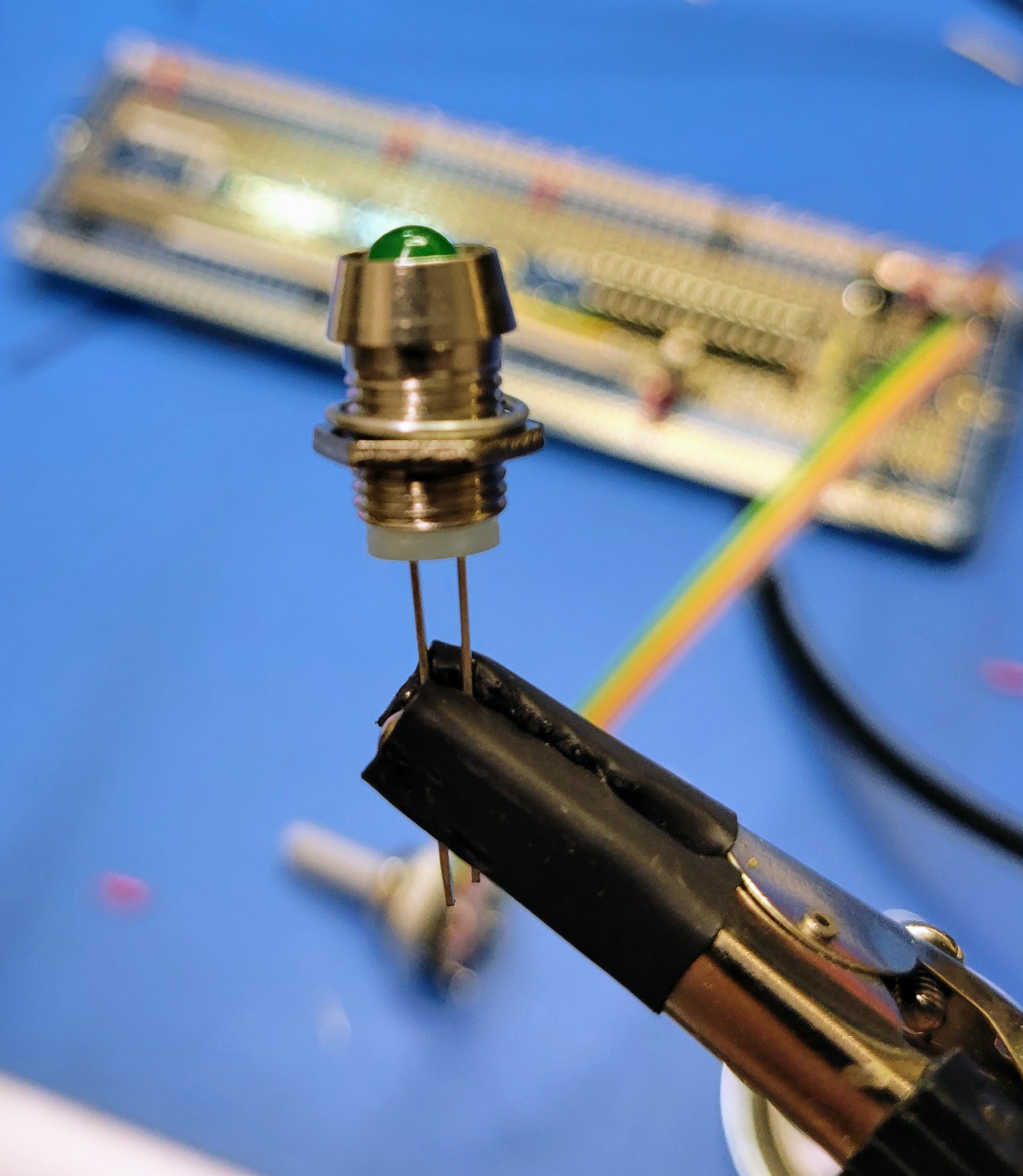
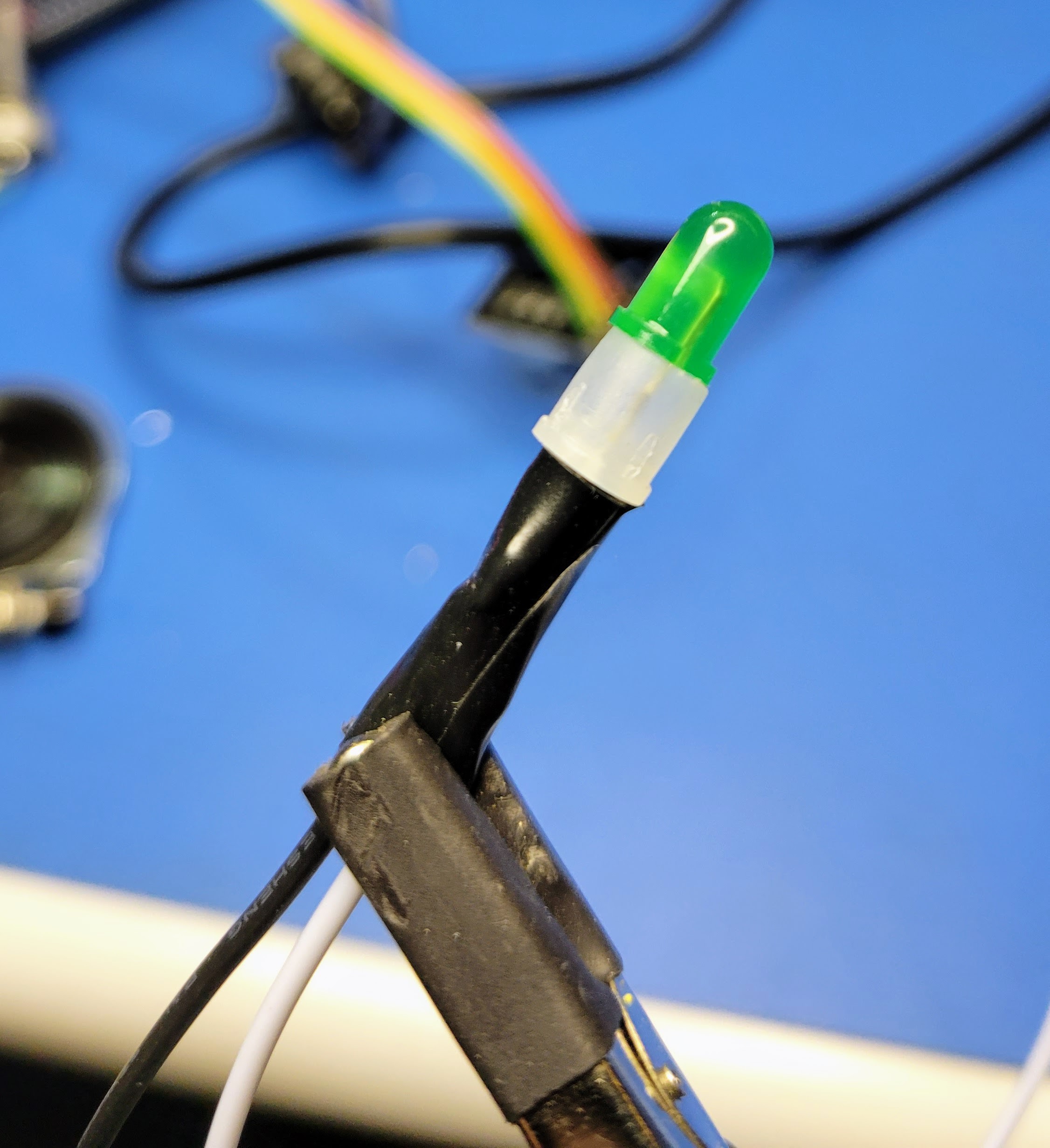
Next wire the result indicator LED to the current limiting resistor (pin 14 on the MCU) installed in a previous log and ground. The positive lead of the LED (the longer lead) will connect to row 53 column A. The negative lead connects to the ground bus.
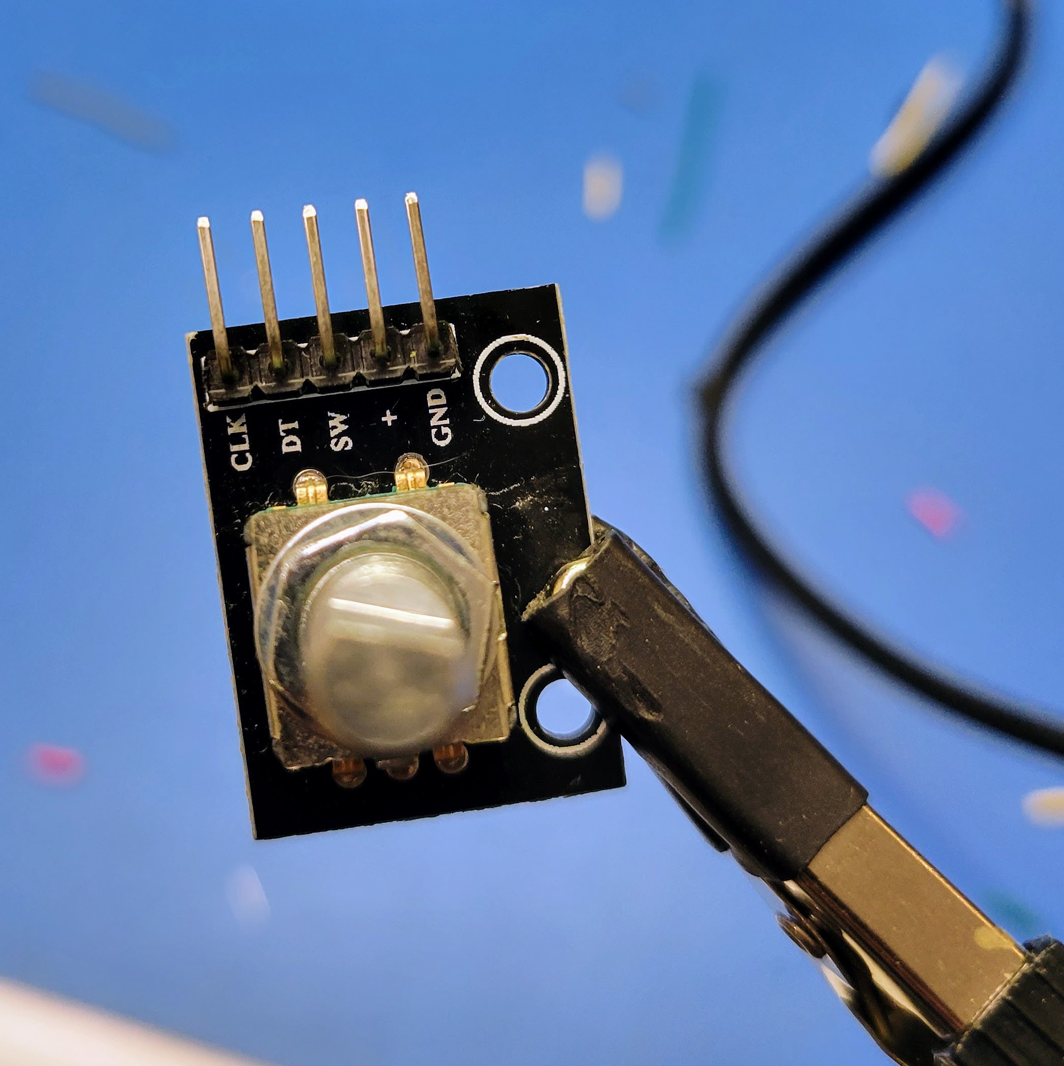
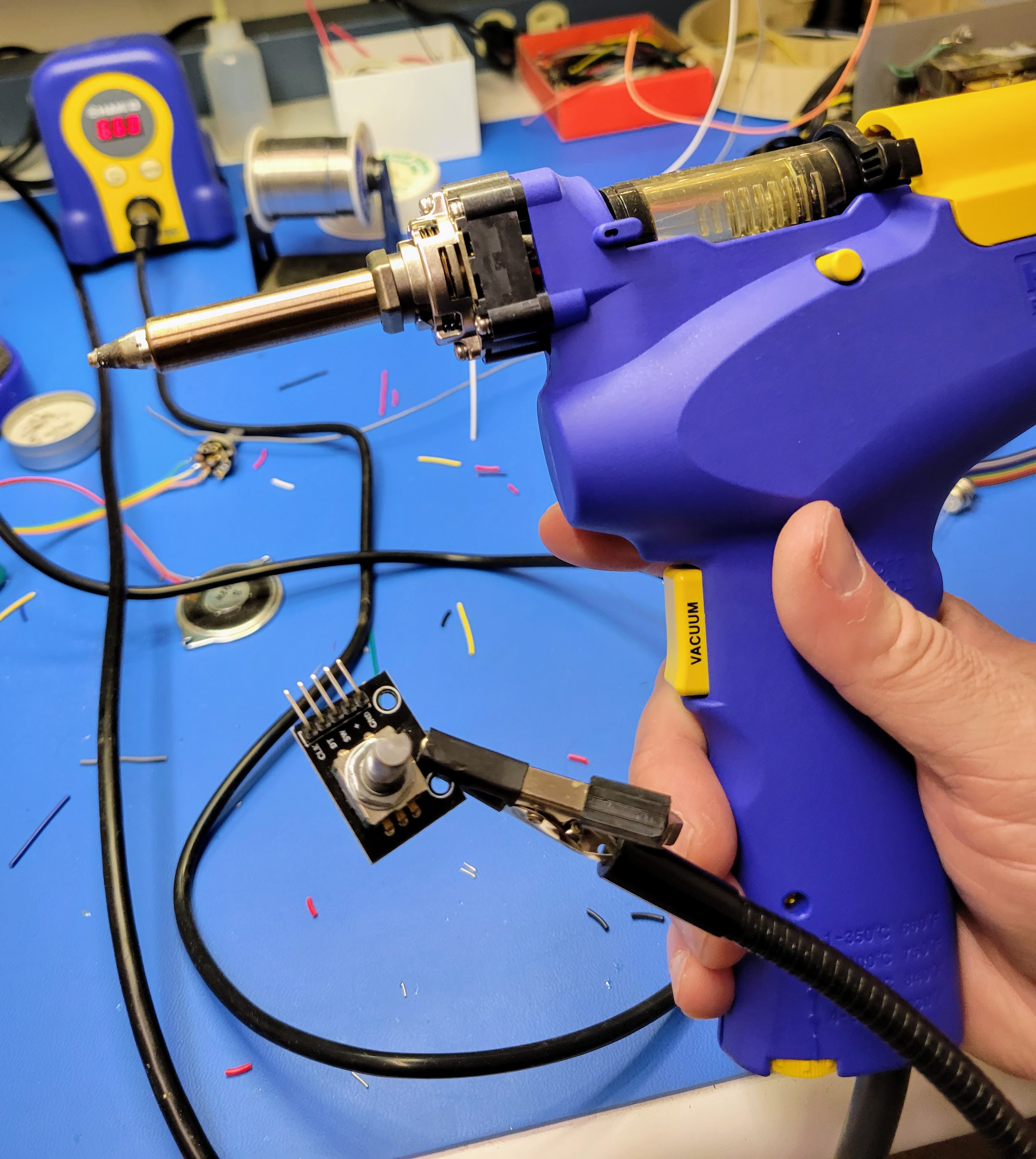
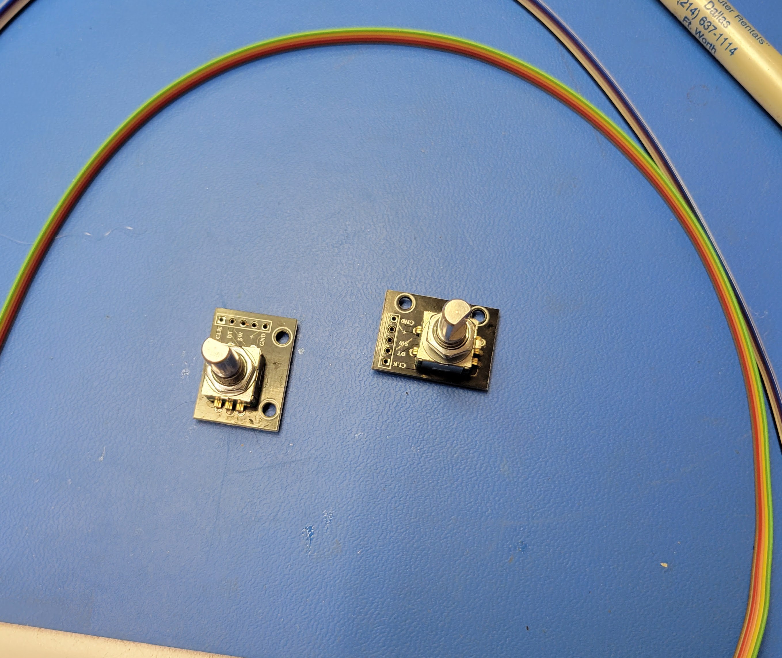
Finally connect the two rotary encoders to the MCU. These will be connected directly to +5v bus, ground bus, and 3 I/O pins. The rotary encoders that I purchase come with inline 5 pin IDC connectors. However, I find it easier to remove this connector with my handing solder sucker and wire the 5 conductor ribbon cable directly to the board.
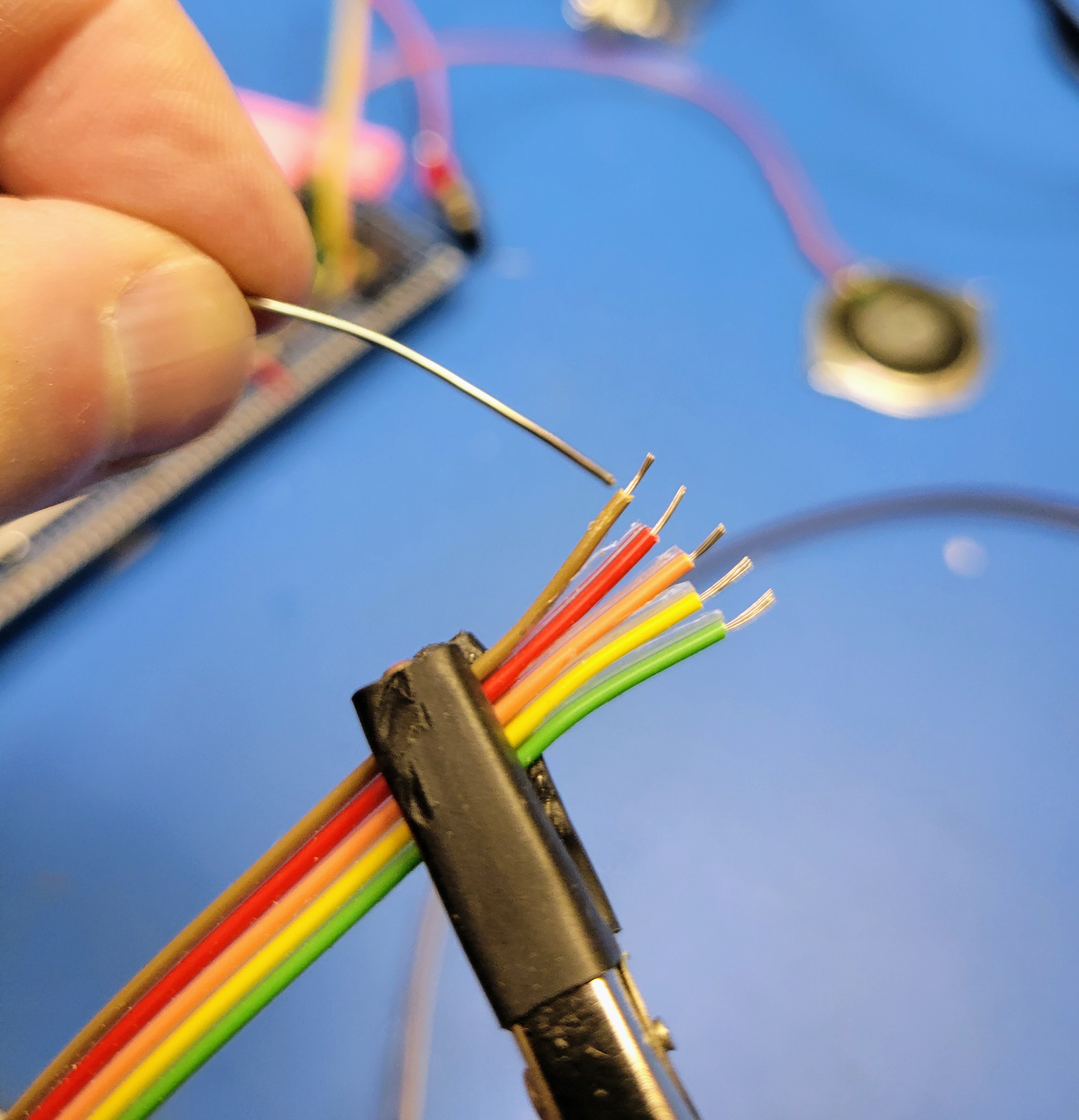
As with other stranded wire, I find it much easier to tin the wire before soldering to the board.
The ribbon cable wired to the encoder board will look something like this.
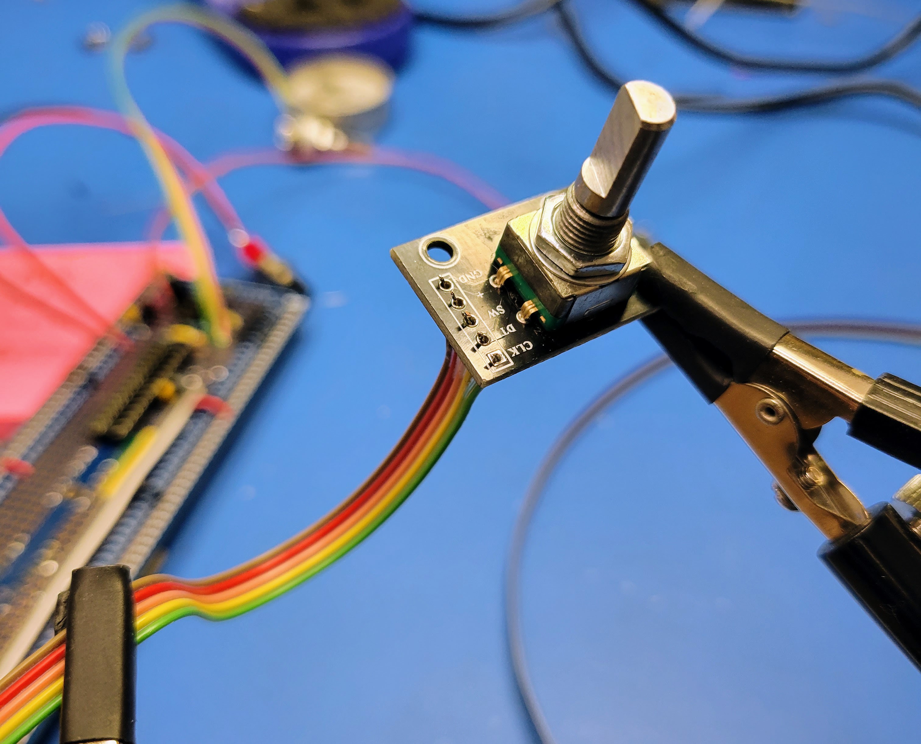
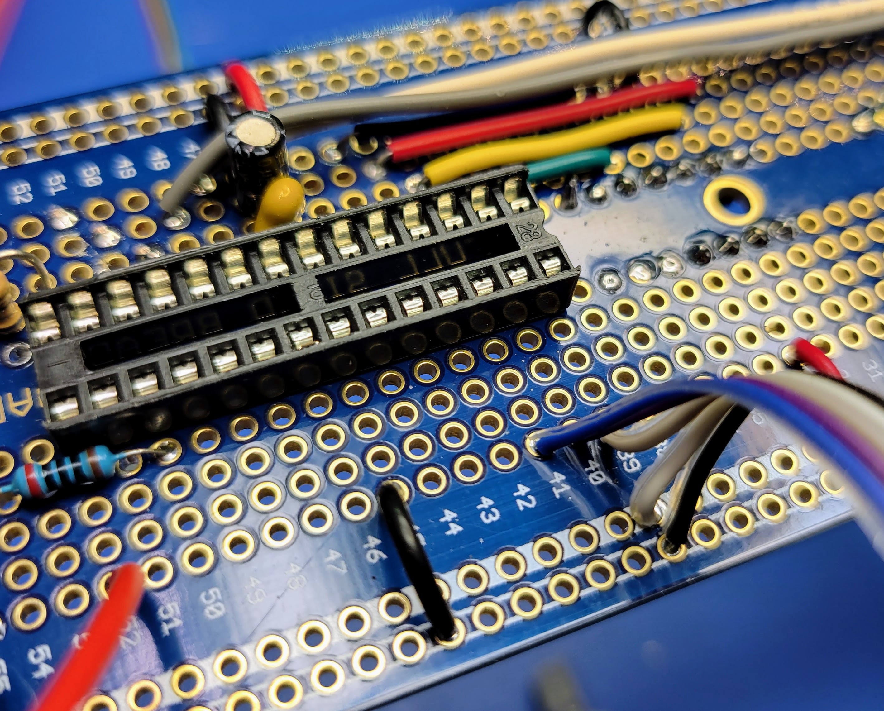
Now the +5v, ground, switch, data, and clock signals will line up so connecting to the MCU is relatively simple. For the dice count encoder:
- SW (switch) to MCU pin 28 (Row 39 Column J)
- DT (data) to MCU pin 27 (Row 40 Column J)
- CLK (clock) to MCU pin 26 (Row 41 Column J)
For the dice type encoder:
- SW (switch) to MCU pin 25 (Row 42 Column J)
- DT (data) to MCU pin 24 (Row 43 Column J)
- CLK (clock) to MCU pin 23 (Row 44 Column J)
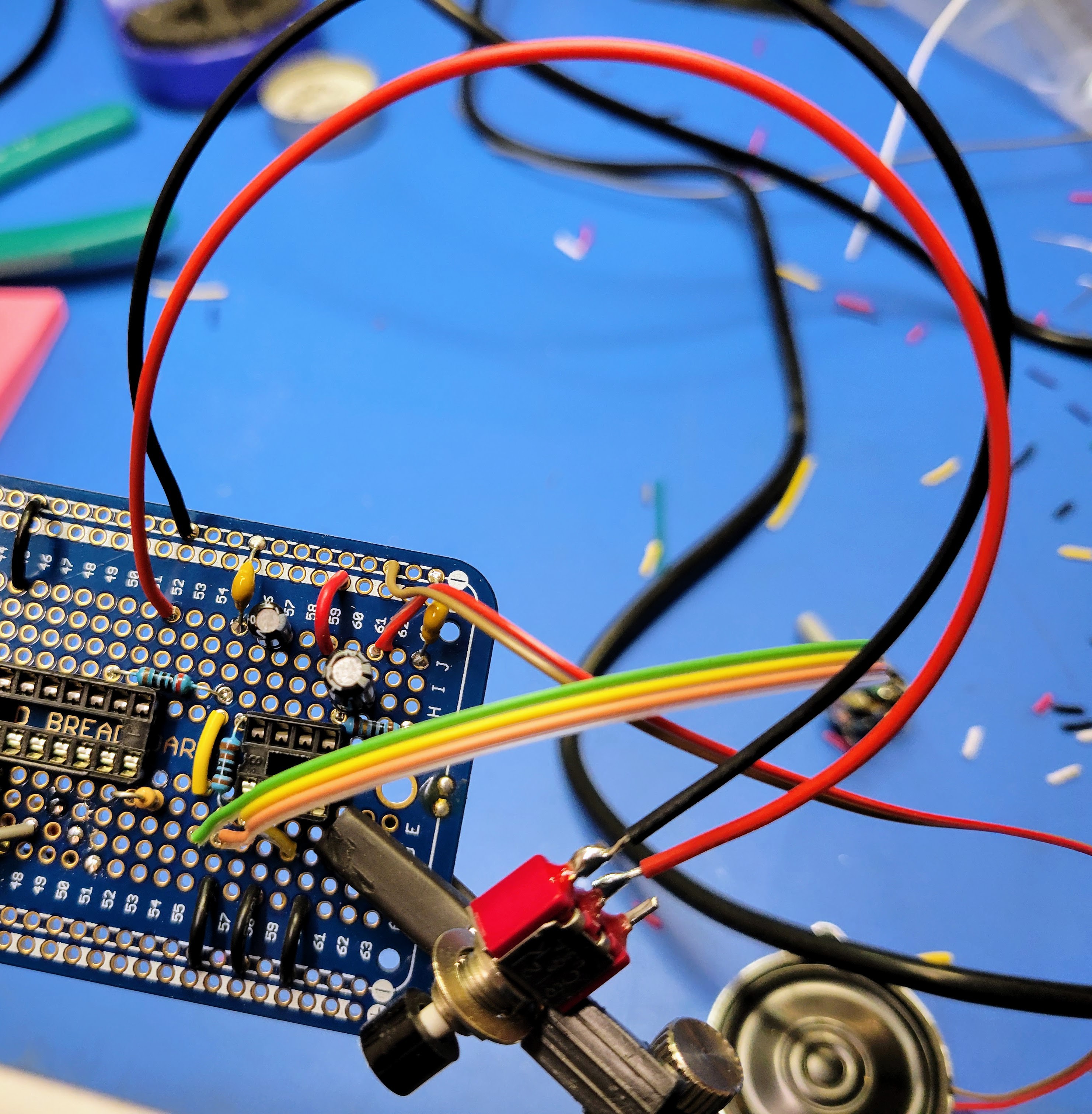
When you are done, your controller board should look like this octopus.
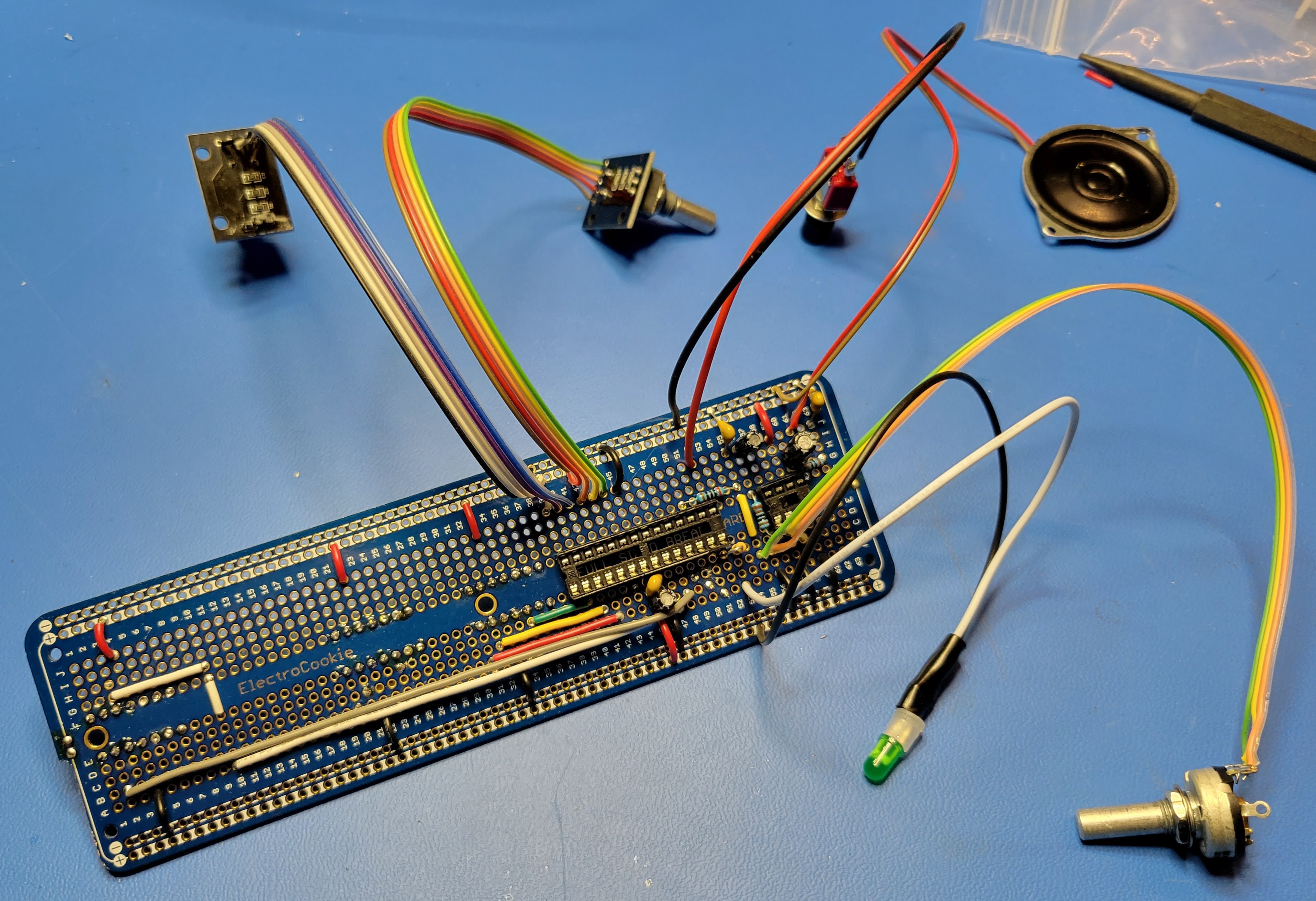
In the next blog, we'll apply face plate graphics, install the controller board, and mount the indicators and controls.
Discussions
Become a Hackaday.io Member
Create an account to leave a comment. Already have an account? Log In.