 Guillermo Perez Guillen
TRANSMITTER SCHEMATIC DIAGRAM
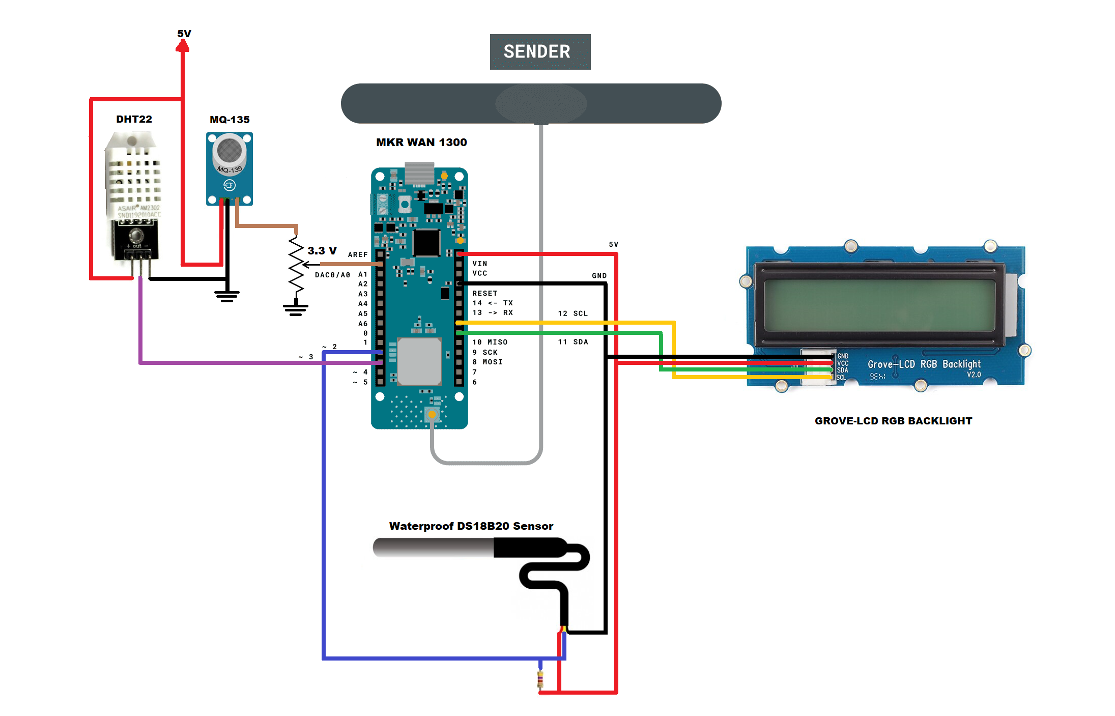
In the figure below I show you the electrical diagram of the transmitter after adding the DHT22 humidity sensor and the MQ-135 air quality sensor.
ADDING THE DHT22 SENSOR
In the figure below I show you the DHT22 sensor.
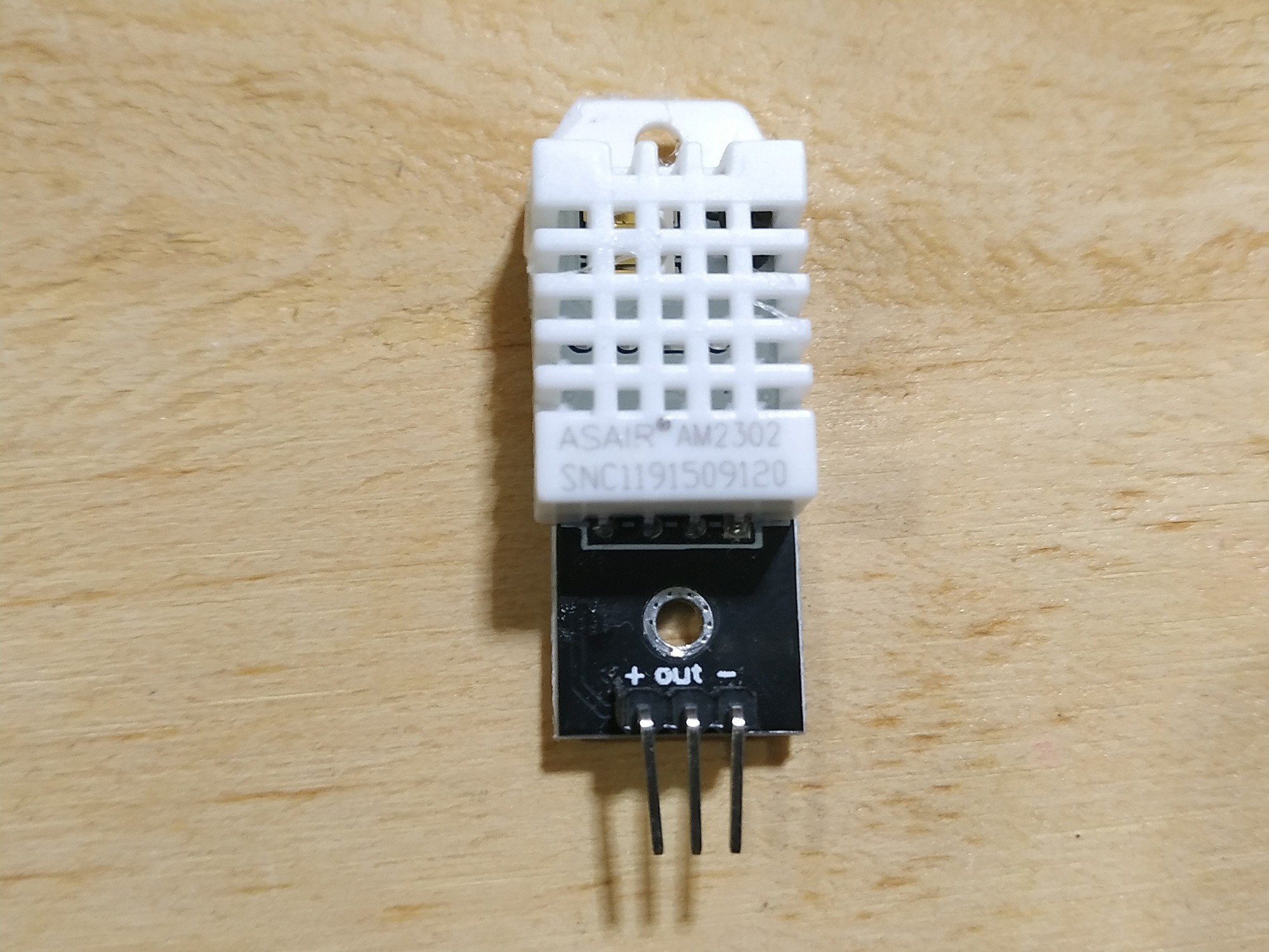
In this sensor I only obtain humidity readings with value ranges between 0 to 100%. I omit the temperature readings as the DS18B20 temperature sensor has a better measurement range (-55°C to +125°C). You can get the library used to program this sensor here: DHT-sensor-library
ADDING THE MQ-135 SENSOR
In the figure below I show you the MQ-135 sensor.

Sensitive material of gas sensor is SnO2, which with lower conductivity in clean air. When target pollution gas exists, the sensor’s conductivity gets higher along with the gas concentration rising. Users can convert the change of conductivity to correspond output signal of gas concentration through a simple circuit.
I use this sensor to detect and measure carbon dioxide (CO2) particles in parts per million (ppm). In the following links you can find the reference information and the code to obtain it:
https://github.com/5cottyD/Projects/blob/master/co2ppm_meter.ino
Since these sensors have small differences, I made a small adjustment to this code to calibrate the CO2 level to 0. This is done in the following line of code:
#define co2Zero 55 //calibrated CO2 0 level
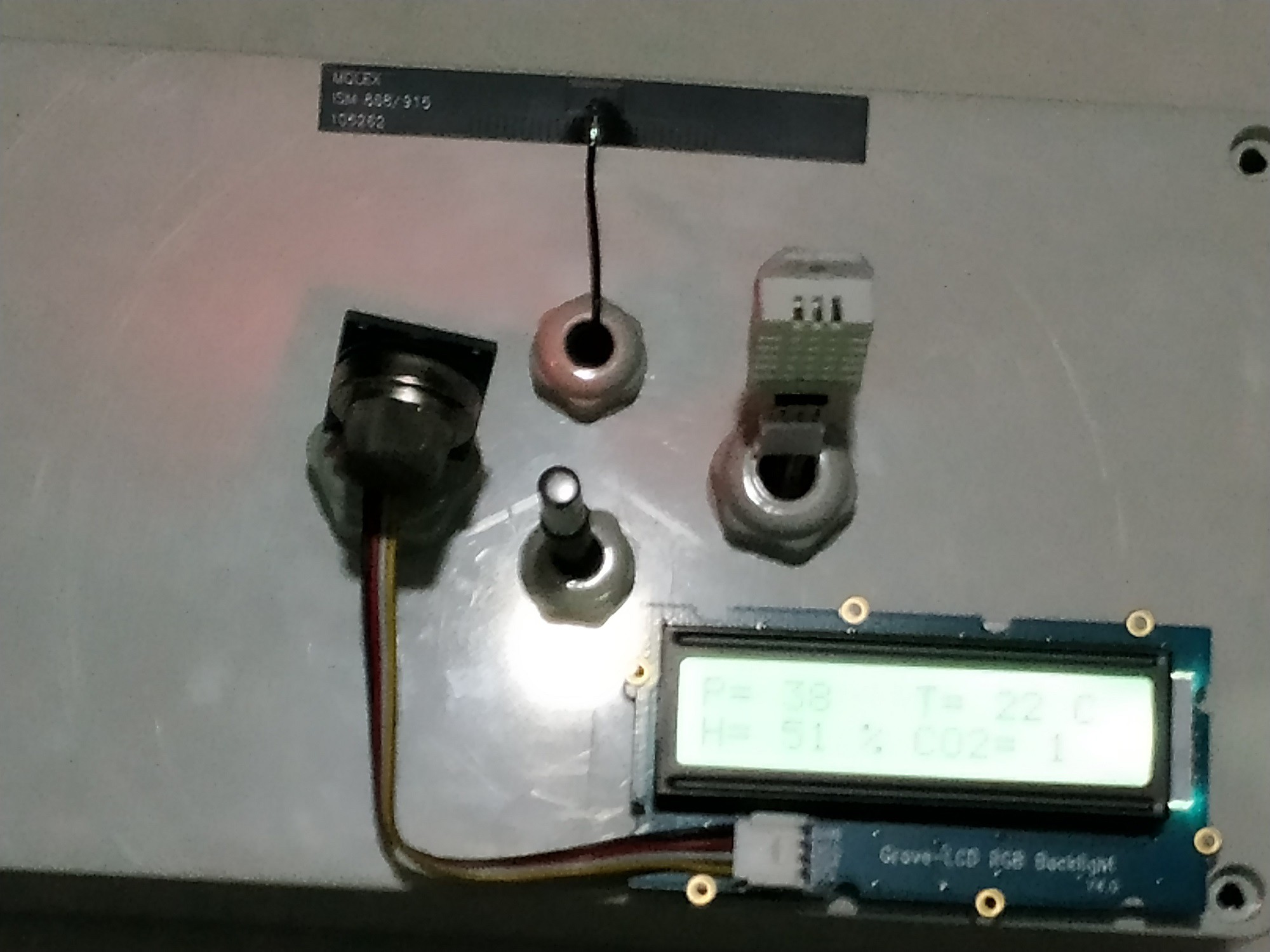
After mounting the three sensors, the device would look like the image below.
TRANSMITTER CODE
After adding the DHT22 and MQ-135 sensors, the transmitter code would be as shown below:
LoRaSender_v3.ino
// AUTHOR: GUILLERMO PEREZ GUILLEN

#include <SPI.h> // LoRa->
#include <LoRa.h>
#include <OneWire.h> // DS18B20->
#include <DallasTemperature.h>
#include <Wire.h> // LCD->
#include "rgb_lcd.h"
rgb_lcd lcd;
const int colorR = 173;
const int colorG = 255;
const int colorB = 47;

#include "DHT.h" // DHT22 ->
#define DHTPIN 3    // Pin where the sensor is connected
#define DHTTYPE DHT22   // DHT22 sensor
DHT dht(DHTPIN, DHTTYPE);

// DS18B20-> Data wire is plugged into port 2 on the Arduino
#define ONE_WIRE_BUS 2
OneWire oneWire(ONE_WIRE_BUS);
DallasTemperature sensors(&oneWire);

#define anInput     A0 // MQ135-> analog feed from MQ135
#define co2Zero     0 // calibrated CO2 0 level

int counter = 0;

void setup() {
  // set up the LCD's number of columns and rows:
  lcd.begin(16, 2);
  lcd.setRGB(colorR, colorG, colorB);
  lcd.print("ECOLOGY!");
  pinMode(anInput,INPUT); // MQ135
  lcd.setCursor(0, 1); // LCD
  lcd.print("LoRa Sender");
  if (!LoRa.begin(915E6)) {
  lcd.setCursor(0, 1); // LCD
  lcd.print("Starting LoRa failed!");
    while (1);
  }
  sensors.begin();
  dht.begin();
}

void loop() {
  int co2now[10]; //int array for co2 readings
  int co2raw = 0; //int for raw value of co2
  int co2ppm = 0; //int for calculated ppm
  int zzz = 0; //int for averaging
  for (int x = 0;x<10;x++) // MQ135-> samplpe co2 10x over 2 seconds
  {
    co2now[x]=analogRead(A0);
    delay(200);
  }
  for (int x = 0;x<10;x++) // add samples together
  {
    zzz=zzz + co2now[x];
  }
  co2raw = zzz/10; // divide samples by 10
  co2ppm = co2raw - co2Zero; // get calculated ppm
  if (co2ppm <= 0) {
    co2ppm = 1;
  }
  else {
    co2ppm = co2ppm;
  }
  int h = dht.readHumidity(); //We read the Humidity
  sensors.requestTemperatures();   //The command to read the temperature is sent
  int temp = sensors.getTempCByIndex(0); //The temperature is obtained in ยบC
  // send packet
  LoRa.beginPacket();
  LoRa.print(temp);
  LoRa.print(",");
  LoRa.print(h);
  LoRa.print(",");
  LoRa.print(co2ppm);
  LoRa.endPacket();
  // LCD display data
  lcd.clear();
  lcd.setCursor(0, 0); // LCD
  lcd.print("P=");
  lcd.setCursor(3, 0); // LCD
  lcd.print(counter);
  lcd.setCursor(8, 0); // LCD
  lcd.print("T=");
  lcd.setCursor(11, 0); // LCD
  lcd.print(temp);
  lcd.setCursor(14, 0); // LCD
  lcd.print("C");
  lcd.setCursor(0, 1); // LCD
  lcd.print("H=");
  lcd.setCursor(3, 1); // LCD
  lcd.print(h);
  lcd.setCursor(6, 1); // LCD
  lcd.print("%");
  lcd.setCursor(8, 1); // LCD
  lcd.print("CO2=");
  lcd.setCursor(13, 1); // LCD
  lcd.print(co2ppm);
  counter++;
  delay(2000);
}
As you can see, the data from the three sensors is separated by a comma(",").
Discussions
Become a Hackaday.io Member
Create an account to leave a comment. Already have an account? Log In.