 Guillermo Perez Guillen
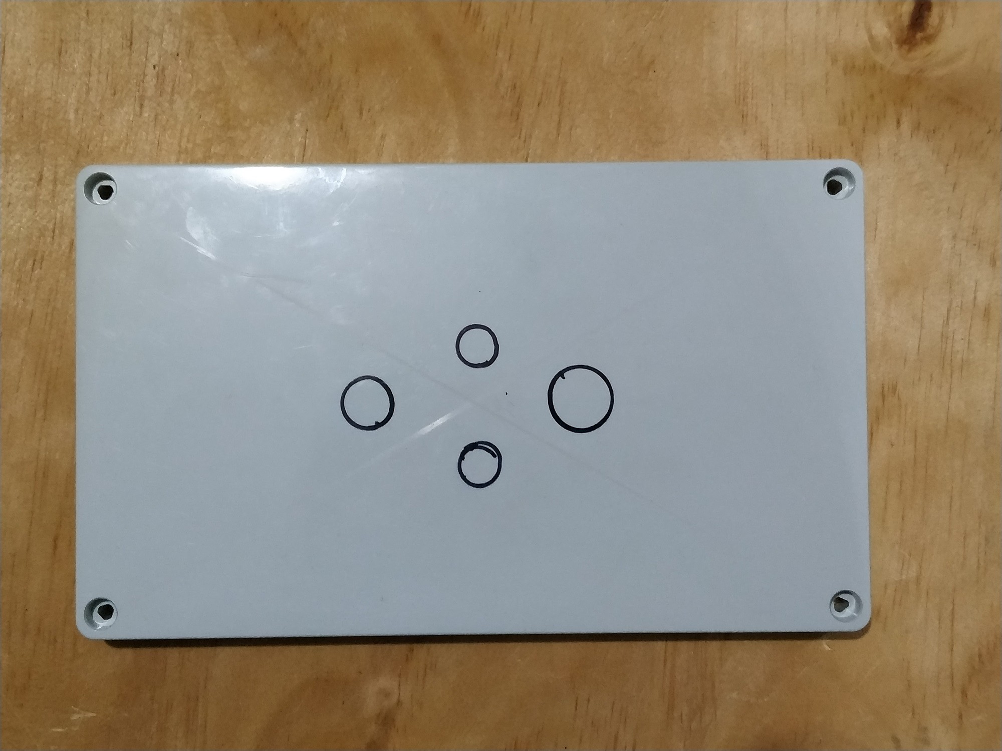
In the figure below I show the lid of the box to make the marks for the drill holes.
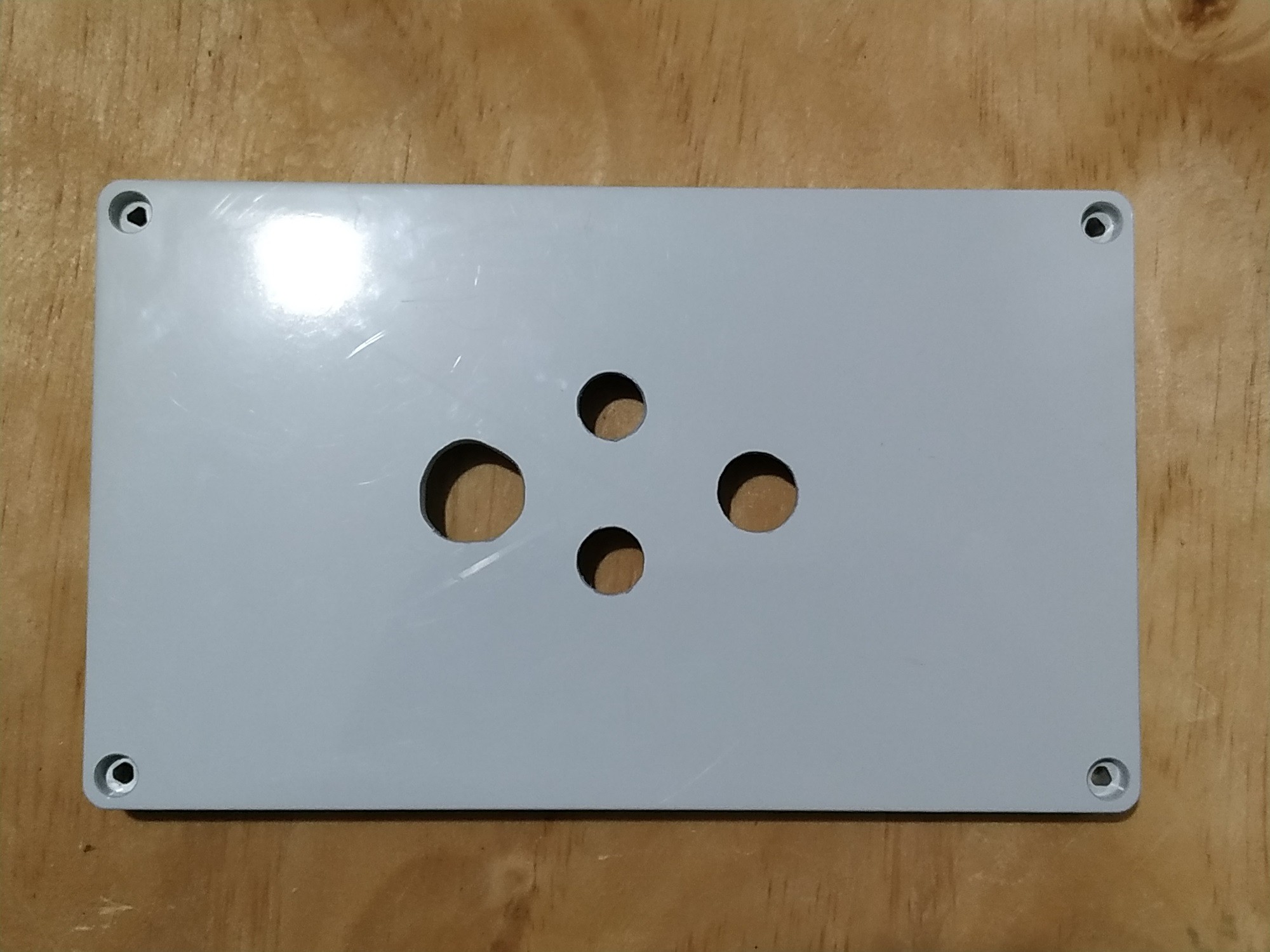
Now below we see how this piece was after drilling.
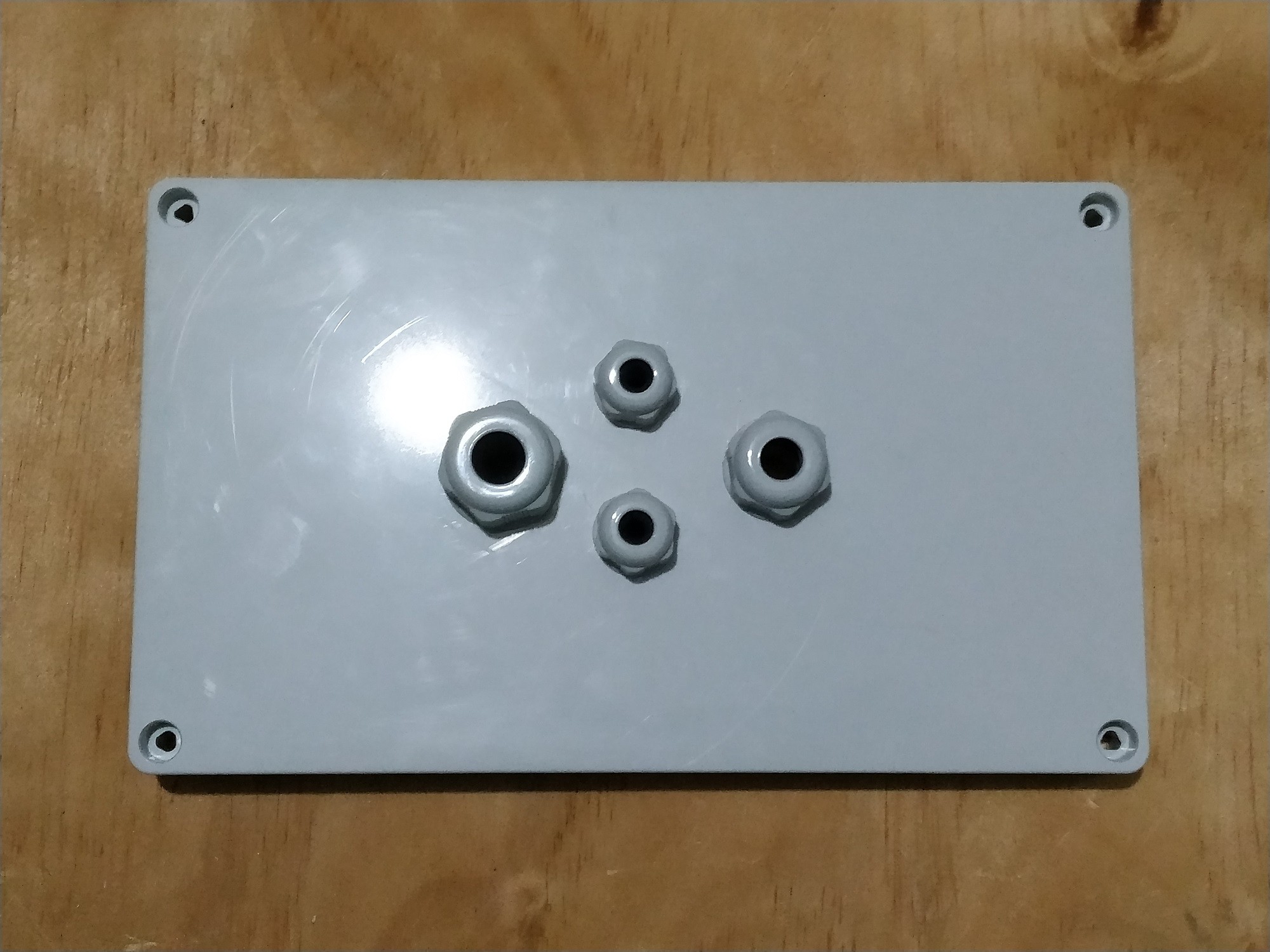
Once the holes are large enough, then it's time to attach the connectors.
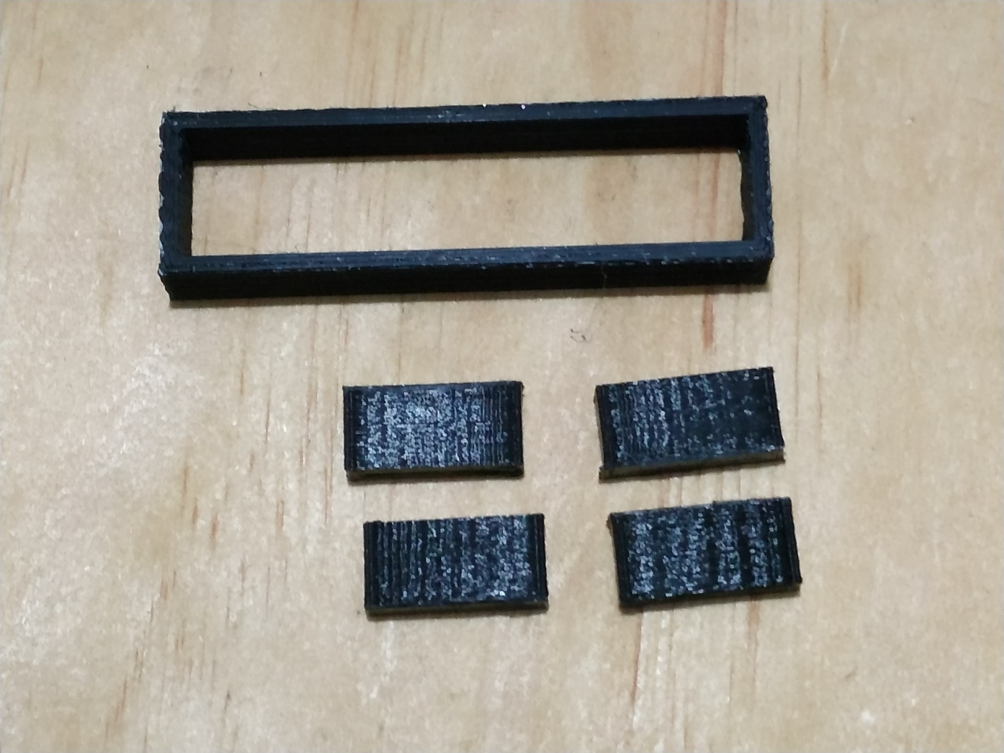
In the figure below I show you the pieces that I print on the 3D printer. These pieces are used to fix the Arduino MKR WAN 1300 board and the LCD display.
In the image below you can see how to assemble the 16x2 LCD display that comes in the kit.
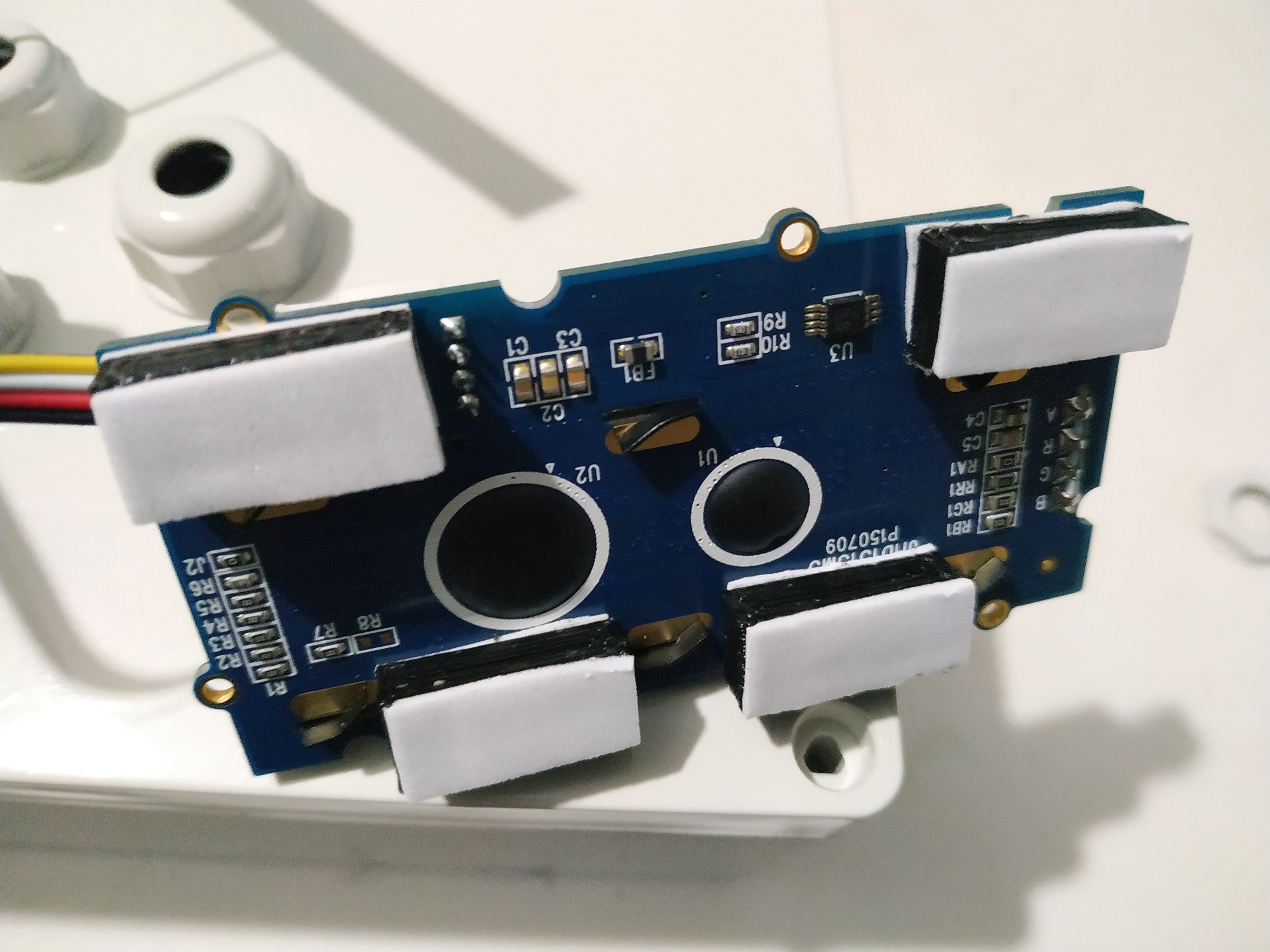
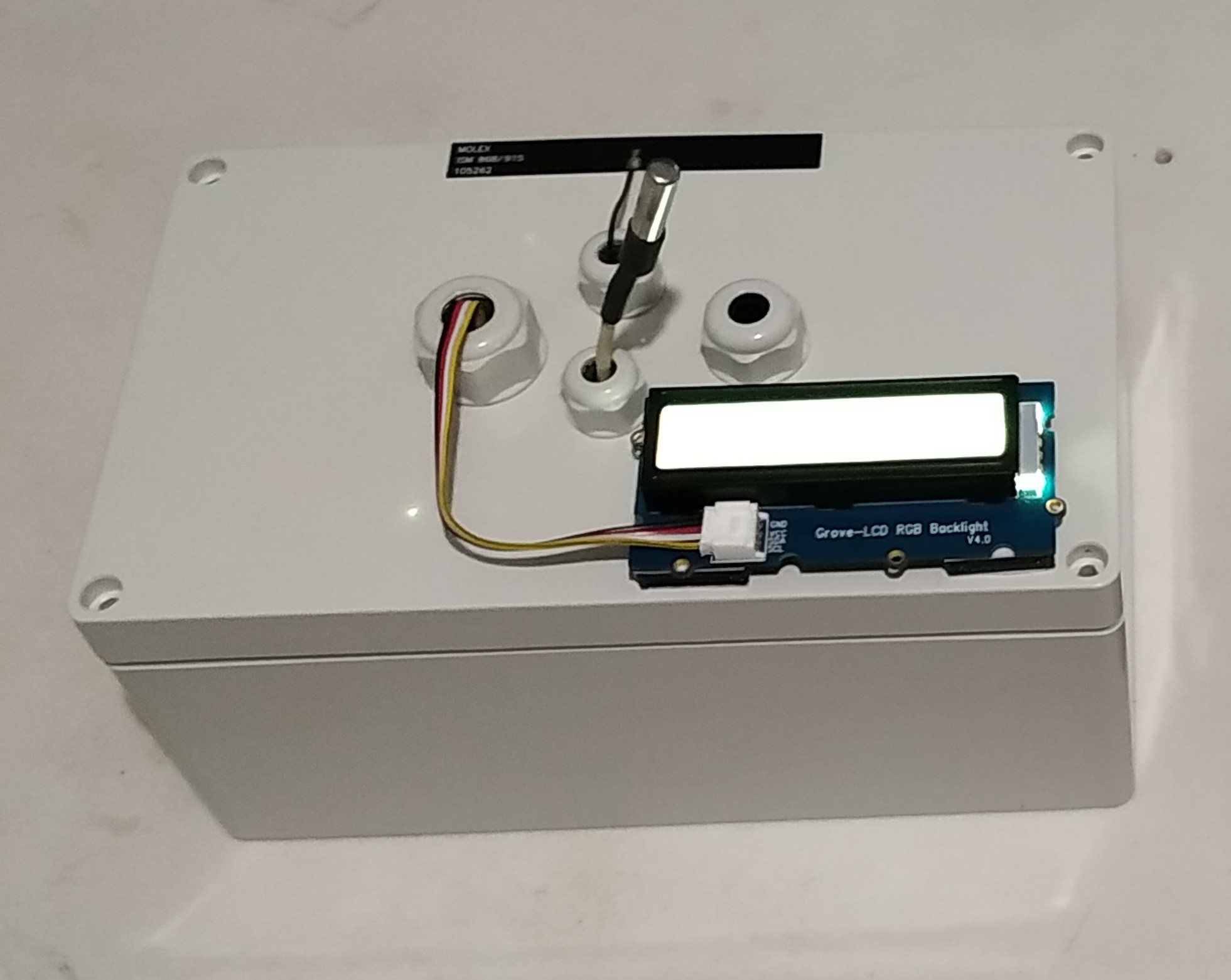
Then we fix the Arduino MKR WAN 1300 board, the 16x2 LCD display, the DS18B20 sensor and the antenna.
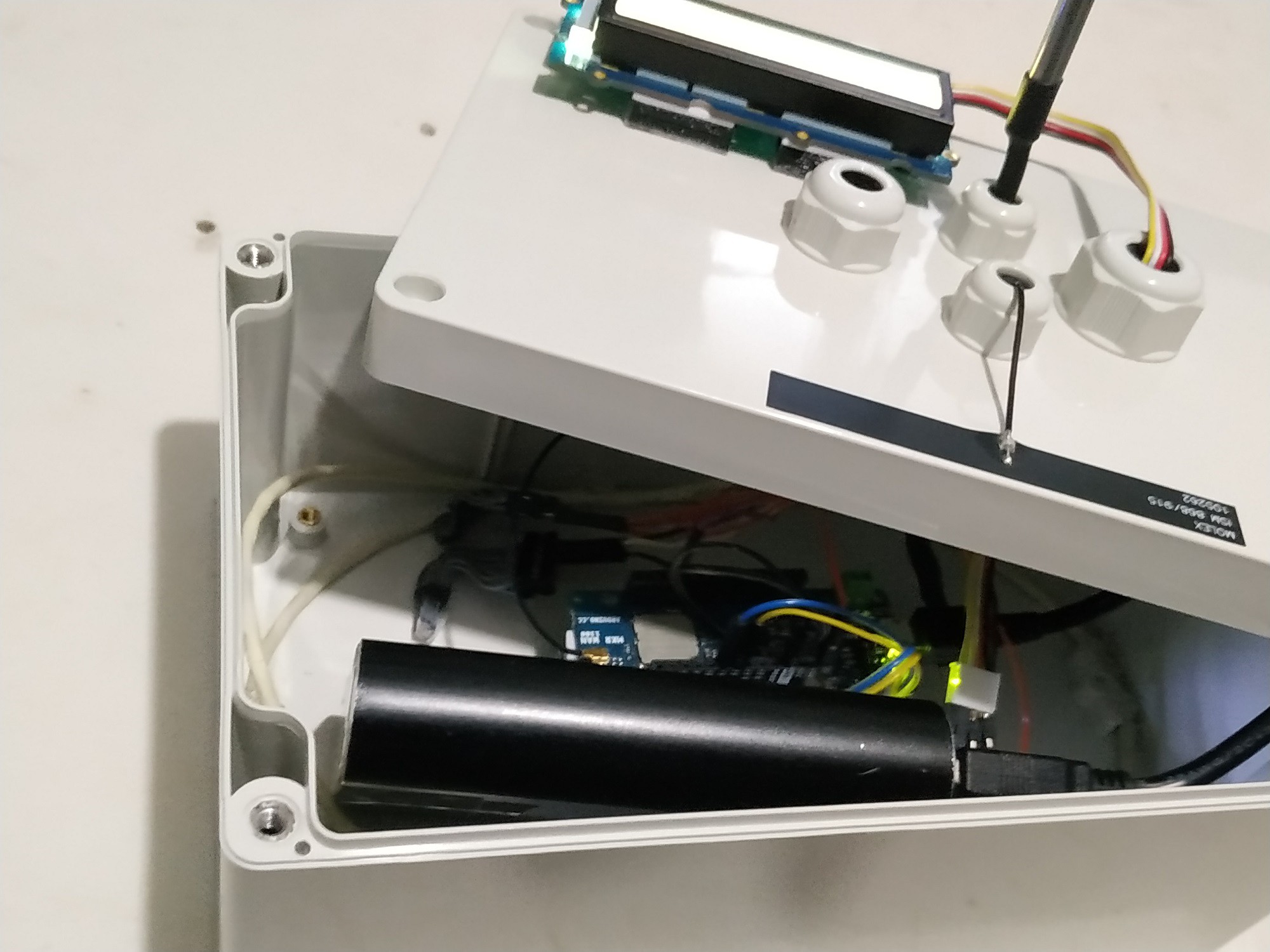
The transmitter would look like the figure below.
As a power supply I used a generic 5V Portable Charger Power Bank 16800 mAh. In addition to providing more accurate voltages, this device gave me better results since it has a power button, a voltage regulator and detects when a device is connected or not.
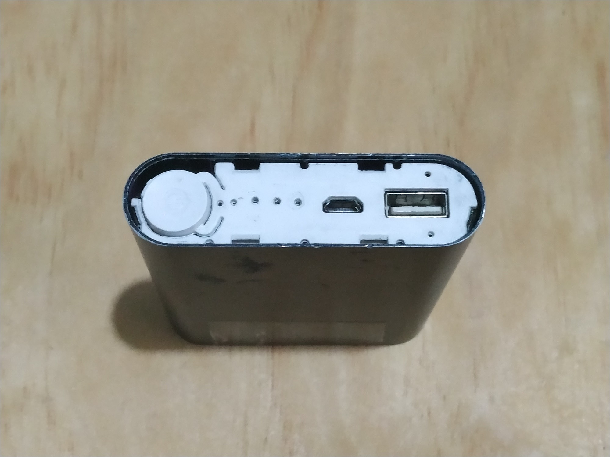
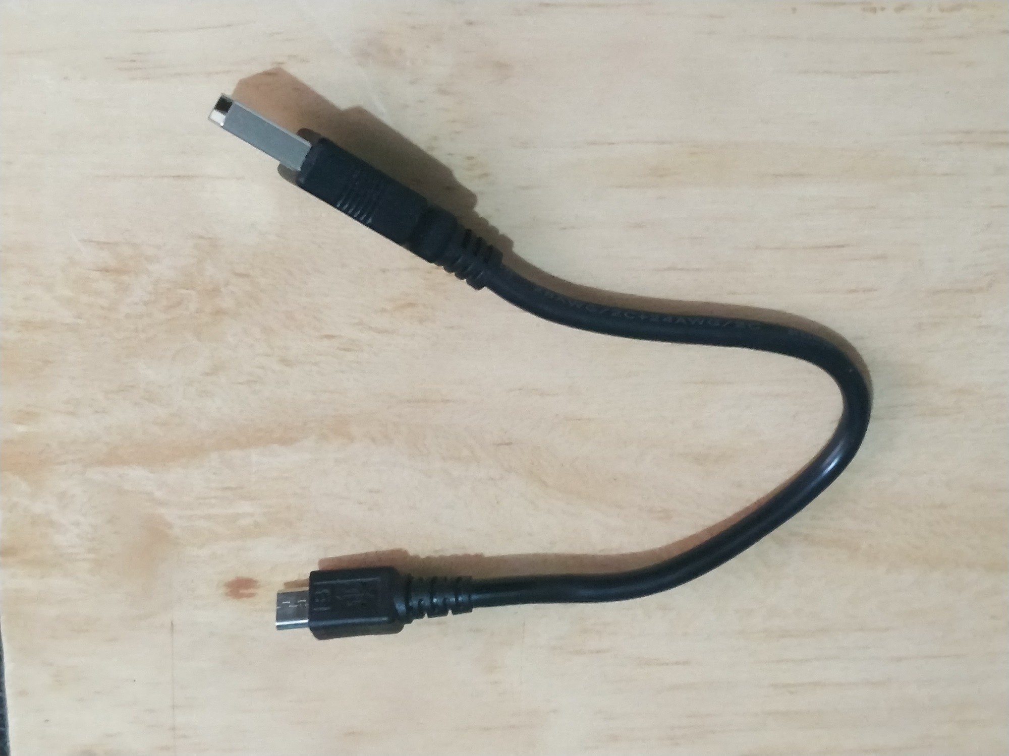
I also recommend using a heavy-duty USB to make a good connection
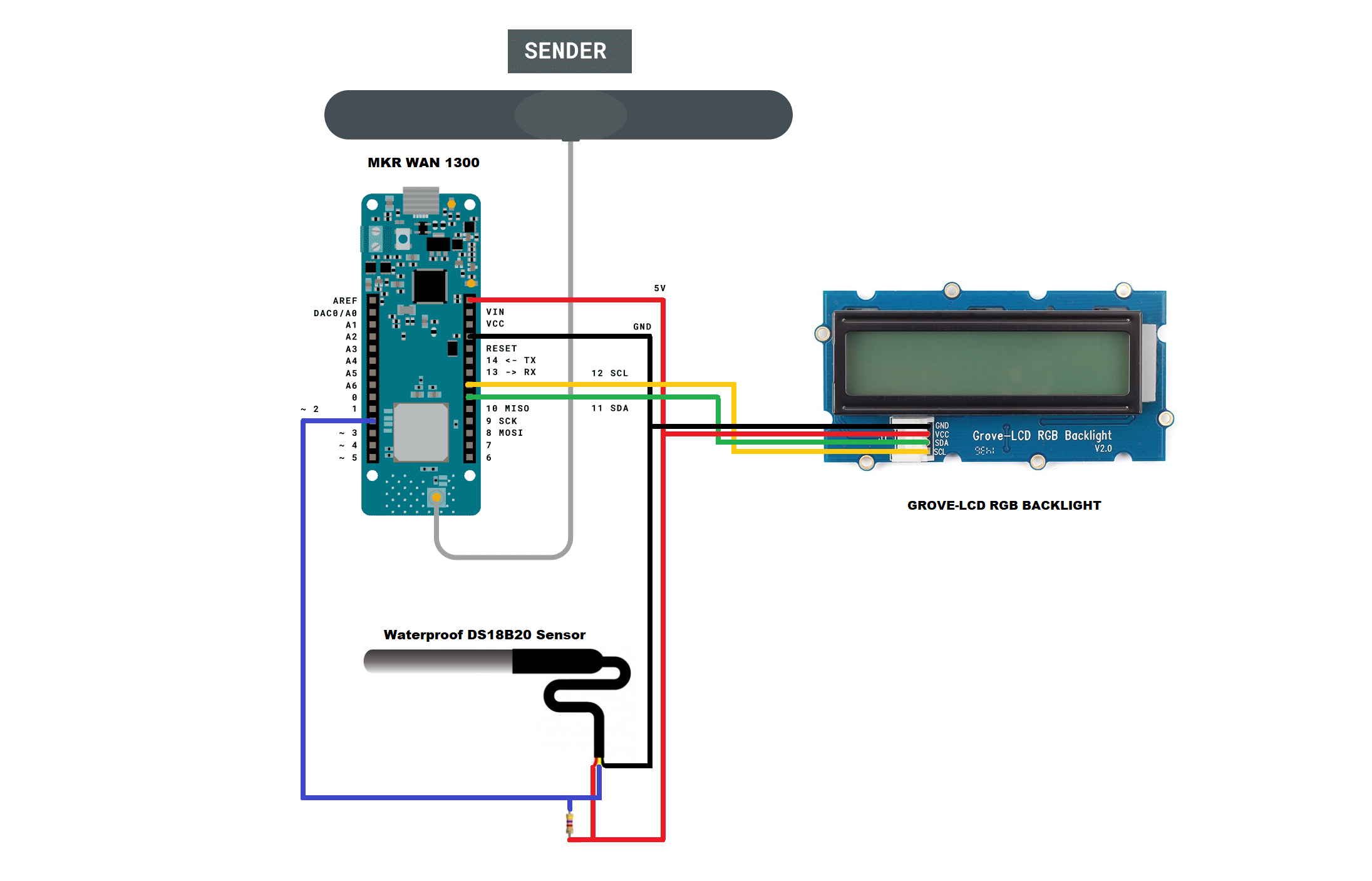
SCHEMATIC DIAGRAM
After adding the 16x2 display, the wiring diagram of the receiver is as shown below.
CODE
All the information needed to install the library you can get in this link: Grove-LCD RGB Backlight Library from Github
After making these changes, the transmitter code is shown below:
LoRaSender_v2.ino
// AUTHOR: GUILLERMO PEREZ GUILLEN

#include <SPI.h>
#include <LoRa.h>
#include <OneWire.h> // DS1B20->
#include <DallasTemperature.h>
#include <Wire.h> // LCD->
#include "rgb_lcd.h"
rgb_lcd lcd;
const int colorR = 173;
const int colorG = 255;
const int colorB = 47;

// Data wire is plugged into port 2 on the Arduino
#define ONE_WIRE_BUS 2
// Setup a oneWire instance to communicate with any OneWire devices (not just Maxim/Dallas temperature ICs)
OneWire oneWire(ONE_WIRE_BUS);
// Pass our oneWire reference to Dallas Temperature.
DallasTemperature sensors(&oneWire);

int counter = 0;

void setup() {
  // set up the LCD's number of columns and rows:
  lcd.begin(16, 2);
  lcd.setRGB(colorR, colorG, colorB);
  // Print a message to the LCD.
  lcd.print("ECOLOGY!");
  lcd.setCursor(0, 1); // LCD
  lcd.print("LoRa Sender");
  if (!LoRa.begin(915E6)) {
  lcd.setCursor(0, 1); // LCD
  lcd.print("Starting LoRa failed!");
    while (1);
  }
  sensors.begin();
}

void loop() {
  sensors.requestTemperatures();   //The command to read the temperature is sent
  int temp= sensors.getTempCByIndex(0); //The temperature is obtained in ยบC
  lcd.clear();
  lcd.setCursor(0, 0); // LCD
  lcd.print("Packet:");
  lcd.setCursor(8, 0); // LCD
  lcd.print(counter);
  lcd.setCursor(0, 1); // LCD
  lcd.print("Temp:");
  lcd.setCursor(8, 1); // LCD
  lcd.print(temp);
  // send packet
  LoRa.beginPacket();
  LoRa.print(temp);
  LoRa.endPacket();
  counter++;
  delay(4000);
}
Discussions
Become a Hackaday.io Member
Create an account to leave a comment. Already have an account? Log In.