 Guillermo Perez Guillen
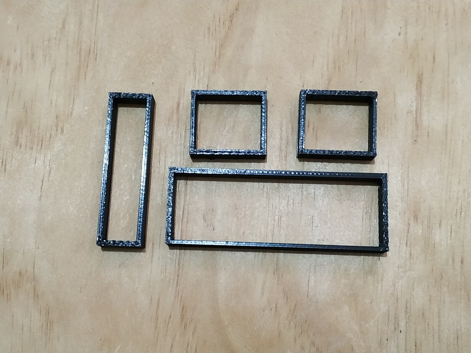
In the figure below I show you the pieces that I print on the 3D printer. These pieces are used to fix the Arduino MKR WAN 1300 board and the LCD display.
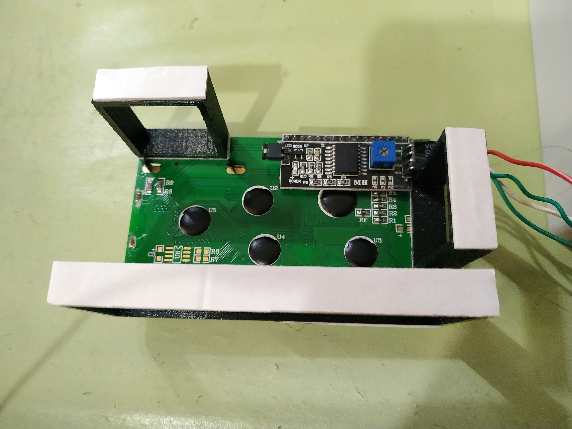
In the image below you can see the assembly of the Arduino MKR WAN 1300 board.

And now in the image below you can see the assembly of the 20x4 LCD display.
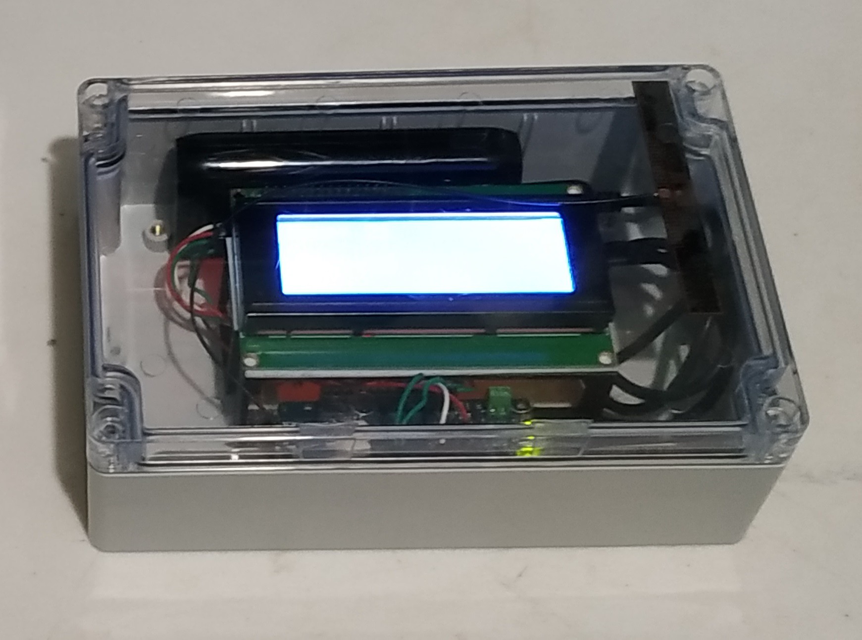
After fixing the Arduino MKR WAN 1300 board, the 20x4 display, the antenna and the battery; the receiving device looks like the one shown in the figure below.
As a power supply I used Anker PowerCore II 6700. In addition to providing more accurate voltages, this device gave me better results since it has a power button, a voltage regulator and detects when a device is connected or not.
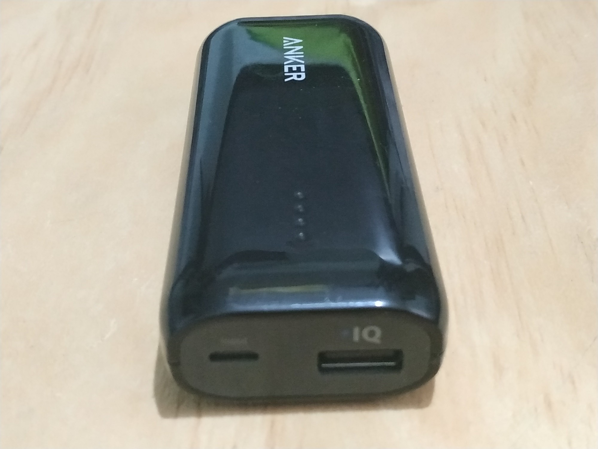
I also recommend using a heavy-duty USB to make a good connection

SCHEMATIC DIAGRAM
After adding the 16x2 display, the wiring diagram of the receiver is as shown below.

CODE
After several attempts to find a library that works well with the Arduino MKR WAN 1300 board, I finally found this one that worked very well for me: LiquidCrystal_I2C
After making these changes, the receiver code is shown below:
LoRaReceiver_v2.ino
// AUTHOR: GUILLERMO PEREZ GUILLEN

#include <SPI.h>
#include <LoRa.h>
#include <Wire.h> // Library for I2C communication
#include <LiquidCrystal_I2C.h> // Library for LCD
LiquidCrystal_I2C lcd = LiquidCrystal_I2C(0x27, 20, 4); // Change to (0x27,16,2) for 16x2 LCD.

char cadena[30]; //We create an array that will store the characters that we will write in the PC console. We assign a limit of characters, in this case 30
byte posicion=0;  //Variable to change the position of the characters in the array
int valor;  //Integer Variable

void setup() {
  lcd.init();  // Initiate the LCD:
  lcd.backlight();
  pinMode(LED_BUILTIN, OUTPUT);
  Serial.begin(9600);
  Serial.println("LoRa Receiver");
  if (!LoRa.begin(915E6)) {
    Serial.println("Starting LoRa failed!");
    while (1);
  }
}

void loop() {
  // try to parse packet
  int packetSize = LoRa.parsePacket();
  if (packetSize) {
    memset(cadena, 0,sizeof(cadena));//memset deletes the contents of the array "cadena" from position 0 to the end sizeof
    // received a packet
    Serial.print("Received packet... ");
    // read packet
    while (LoRa.available()) {
      char dedos= (char)LoRa.read();
      Serial.print(dedos);
      cadena[posicion]=dedos;//Read a character from the string "cadena" from "posicion", then read the next character with "posicion++"
      posicion++;
    }
    valor=atoi(cadena);//Convert the string to integers
    Serial.println();
    Serial.print(" temp=");
    Serial.print(valor);
    posicion=0;
    // print RSSI of packet
    int dedal = LoRa.packetRssi();
    Serial.print(" with RSSI: ");
    Serial.println(dedal);
    lcd.clear();
    lcd.setCursor(0, 0); // Set the cursor on the first column and first row.
    lcd.print("Temp:");
    lcd.setCursor(6, 0);
    lcd.print(valor);
    lcd.setCursor(0, 2); // Set the cursor on the first column and second row.
    lcd.print("RSSI:");
    lcd.setCursor(5, 2); //Set the cursor on the fifth column and the second row (counting starts at 0!).
    lcd.print(dedal);
    digitalWrite(LED_BUILTIN, HIGH);
    delay(2000);
    digitalWrite(LED_BUILTIN, LOW);
  }
}
Discussions
Become a Hackaday.io Member
Create an account to leave a comment. Already have an account? Log In.