Our Can Sat received the Outstanding Science Mission award. It recorded the air temperature, and pressure in order to fulfill its primary mission. We would have used the pressure to calculate the altitude, and we expected the temperature to drop as altitude increases. For our secondary mission, the Can Sat was supposed to record the PPM of NH3, and the air quality. Using the collected data, we would have studied the change in pullutants as the altitude increases. Although due to some hardware problems unknown to this day, most of the sensors partially or completely failed right during flight, but we managed to successfully correlate our data set with other existing ones which were relevant.
Team
- Cosmin Dumitru - hardware, software
- Victor Arseniu - software, data analysis, mechanical structure
CanSat Hardware
For our current application, we have decided split the features of our CanSat across 5 PCBs, which we will be calling "modules" from now. They communicate which each other through Molex PicoBlade connectors. We have chosen these connectors due to their size and durability.
- Power Supply Module: offers the main +5V power supply from the LiPo battery, as well as charging circuitry via USB and power-management software which prevents over-discharging and receives shutdown commands, using an ATtiny212.
- Microcontroller Module: acts as the brain of the CanSat. It houses the Raspberry PI Pico development board, the SD card and provides access to the Sensor, Communication and Storage & Buzzer modules.
- Communication Module: monitors the location of the CanSat using GPS (NEO-6M) and sends SMS messages to the “Ground Station” using the M590E GSM chip.
- Backup Storage & Buzzer Module: has the role of storing the flight data of the CanSat on an EEPROM chip and emitting a sound in order to ease the process of localizing the satellite.
- Sensor Module: contains all the sensors the device will sample data from, during its mission:
-
- MQ-135, MQ-137 and MG811 sensors for detecting air quality and the level of Ammonia and Carbon dioxide in the atmosphere, in this order.
- DHT11 humidity sensor
- BMP180 pressure and temperature sensor
- MPU6050 accelerometer and gyroscope sensor
- LM358 operational amplifier for amplifying the output signal of the CO2 sensor, in order to give more accurate readings on the 12-bit ADC of the RP2040. Its gain is set to ~8.5V/1V. According to the MG811 CO2 sensor’s datasheet, its output voltage can reach up to ~350mV, so the maximum voltage fed through the RP2040’s ADC pin will be around 3V.
- P-channel MOSFETs for controlling the 5V and 6V power supply lines for the heating elements of the pollutant sensors from the Raspberry PI Pico, in order to reduce the battery consumption after the data collection process ends. This method did not work since we could not control the MOSFETs from the Pico, so we resorted to using 2 PNP transistors.


Recovery system
For the parachute’s design we will be using garbage bags as they are cheap, and strong enough for bringing the CanSat safely to the ground. We will use a conical parachute with a steep angle, and a hole in the middle the size of the Can
Sat to provide clearance for the GPS antenna. This design should have a drag coefficient between 0.8, and 0.96.
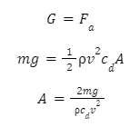
Considering the CanSat’s mass of 300g, and the fact that the intended descent rate of the CanSat is 9.5 m/s, we can calculate the area of the parachute by considering the equilibrium in Newton’s second law of motion:
Plugging in the numbers, we end up with the needed parachute area for the CanSat, and that is between 0.055 m2, and 0.066 m2. Therefore, the ideal parachute area should be about 0.05 m2. The parachute will be mounted with strings on the top mounting plates of the side walls.
CanSat Structure
The CanSat’s body will be made up of 4 main parts: a base plate, a top plate, and 2 wall halves. The PCBs will be held together with M3 screw threads passing through some 3D printed spacers. The whole PCB assembly will be mounted with other 4 spacers on the bottom of the top plate, while the wall halves will be held between the 2 plates with screws passing through wall screw mounts. The parachute will be attached to the top spacers using strings, and also some tape to secure the knot in-place. For air to be able to reach the sensors, the top plate has a hole in the middle. All parts other than the screws, threads, and nuts will be 3D printed from PET-G.
Each spacer has a hexagonal shape with a non threaded hole slightly narrower than needed for the screw to fit. This way, we can force a screw through the hole in order to create the thread, as it would have been too much detail for 3D printing. In total, there will be 20 spacers used, 4 sets of 4 to separate the PCBs, and another set of 4 longer spacers to attach the PCB assembly to the top plate.


Conclusion
We enjoyed participating in the competition, and we’re glad to make it to the end, even though we couldn’t really complete any of our primary, nor secondary missions. However, this doesn’t mean we lost anything, in fact we only gained experience, and learned a lot about working as a team, and getting a project from the state of a concept to an actual physical thing, while having fun through it all.