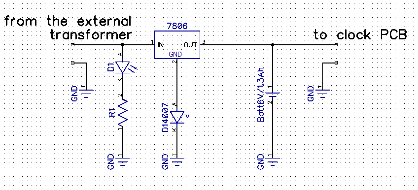
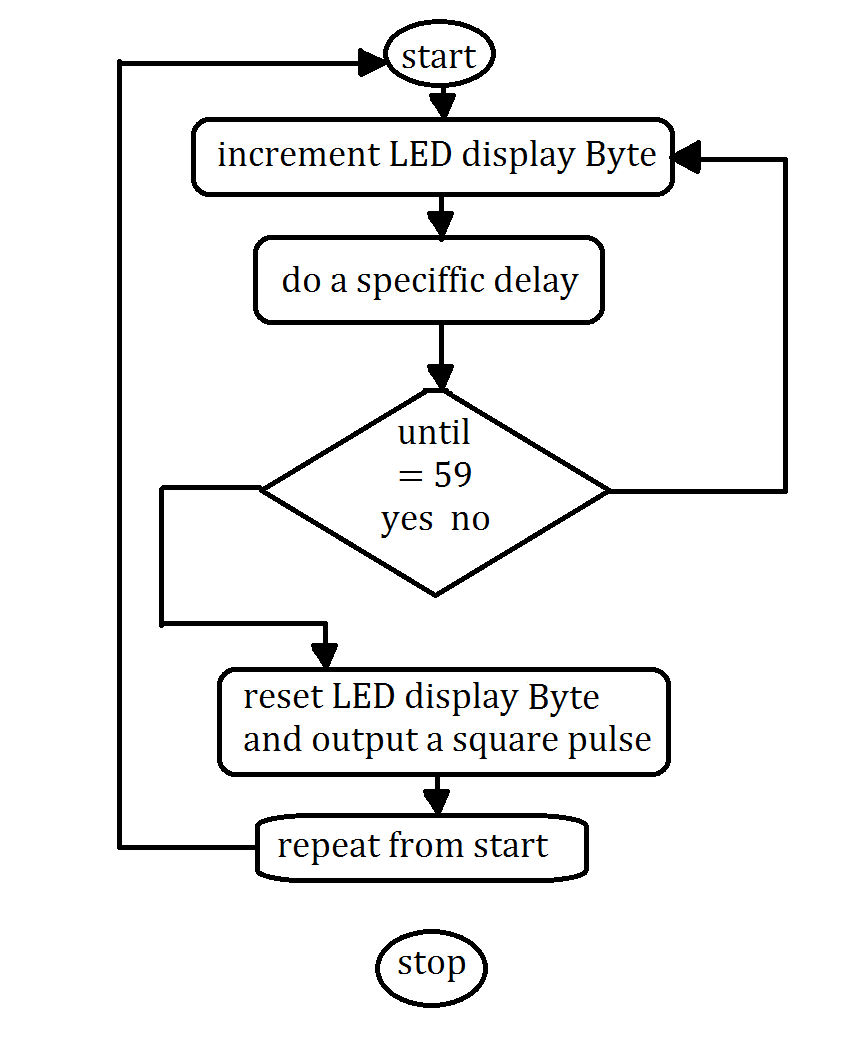
I didn’t wanted to struggle very much with a RTC and since I had a previous MCU project that was generating a 1s pulse, I thought I use that as a master circuit for my clock. I could have used the tmr modules of the same MCU, but then I realized I had to use another external CLC chip just to increase the number of pins because I wanted to build the binary LED display for the seconds. Since I found that these China MCUs are cheaper than many other 74’s, I decided that I was going to use this configuration of two microcontrollers. So I came up with this twisted-head schematic eventually. The master circuit also controls the seconds display and after it finishes displaying all the LEDs and measuring exactly one second, it outputs a single pulse from the pin D7 of the PortB. This pulse is the increment signal for the slave chip and the chip knows exactly what to do with it.
The code on the master MCU is really minimalist and with some small exceptions regarding the order of the instructions and without the conversion procedures, it could be described like this:
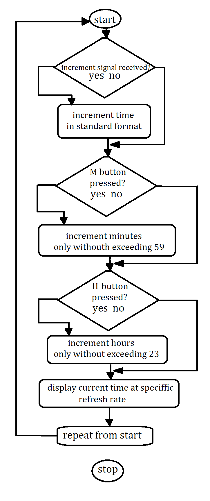
The slave MCU then picks up the square wave from the master and increments the rest of the clock... and without trying to be too boring, I will place a simplified flowchart of that too:
Code size
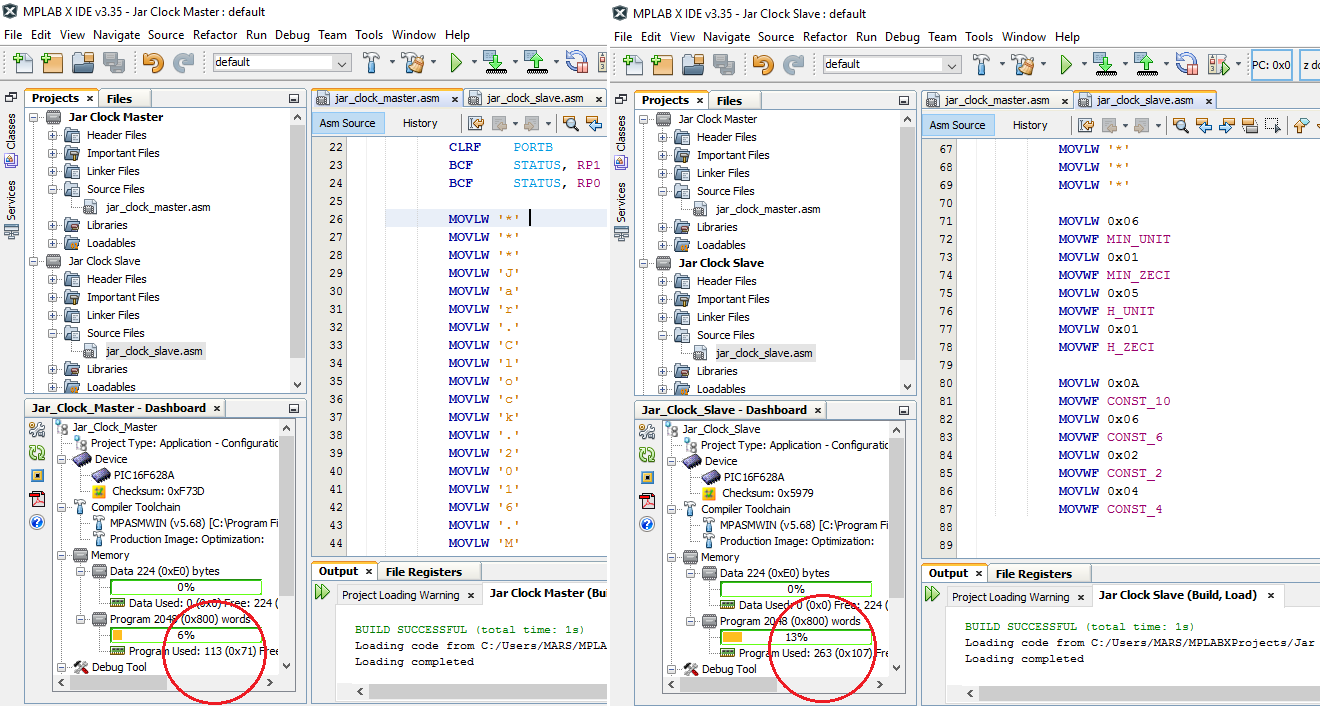
The Master MCU code is only 113 words and the Slave MCu code is 263 so the entire code is 376 x 14 bits.
 Marius Taciuc