The remote finger
In this period I work in "remote working". Of course, I have all the electronic and computer equipment in my little apartment and I can do almost anything from here. The only thing I can't do is turn on the company's notebook, without having to call someone to do so. Unfortunately, the notebook does not have a BIOS setting to tell it what to do when connected to power. I've done a lot of experiments, but if you don't press the button, there's just no way to turn it on. So I thought, since I am a "remote worker", to make a "remote finger" that presses for me, when I want it, the small button on the company notebook. Here is the circuit:

I used an ATtiny24 micro for no particular reason. I just had one in DIP and used it. The program is very simple. I wrote it in C and compiled it with IAR's Embedded Workbench (free registration for download). I downloaded the version with no time limit, but limited to 4KB of flash, which is more than enough for a lot of applications at this level.
How does it work?
At reset, by giving 5V on the USB socket or by pressing the small button (during the tests) the circuit drives the servomotor in a clockwise or anticlockwise direction, as a function of a jumper. This is because, mechanically, you will have to position the servomotor on the body of the notebook and therefore it is better to have the choice. Then there are two trimmers, which are used to adjust the rotation angle (always for the same reason) and the pause time on the set angle, in practice the time for which the "finger" must press the button. After this time, the servo returns to the rest position and the program stops waiting for a new reset.
How do I do it remotely?
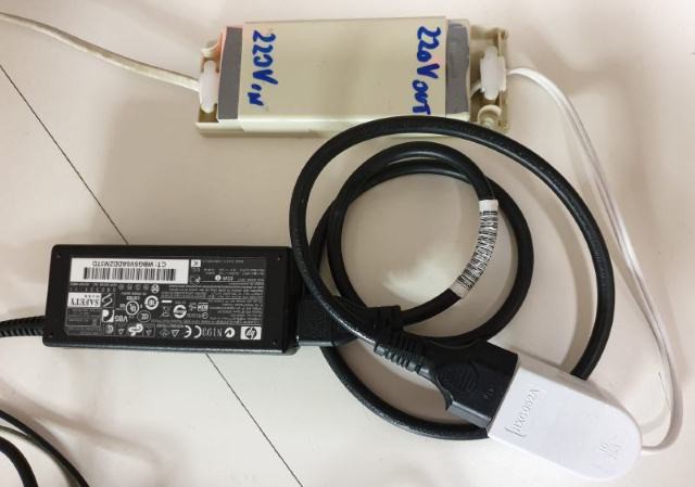
Well, during my tests I used an internet switch to give 220V to the notebook power supply (you can find, in some of my old articles on my website ficara.altervista.org, the description of various of my experiments and circuits that perform this function). Here is the one used in this case. It is very old and is based on a micro ATtiny841 and an ESP-01 wifi module with AT commands:

When I send the ON command via the browser on my PC (at home), the remote switch clicks and the notebook power supply is connected to the mains voltage. As I said, this is NOT enough to turn on the notebook, but (thanks Heaven) the 5V turns on over the USB ports of the notebook. Now, the circuit is connected to a USB port and then it is powered, thus moving the servo motor and making it "press" the button, then the notebook turns on and I can control it remotely via a normal VNC. To shut down, I do it from VNC or remote computer and then, with another browser command, I also turn off the internet switch and thus remove the mains voltage from the notebook power supply. In this situation, everything is ready to start a new session.
Here is the schematic, drawn by hand because I think this will remain a "unique model":

Note: between the Vcc and Gnd pins of the micro there is a 100nF that I missed in the drawing. The prototype was fixed to the notebook in the Company. My friend Rossano (incidentally, the founding partner of the Company) took the photos that I am attaching, as well as physically fixed the circuit to the computer. What can I say… it works perfectly! 🙂
The servomotor pressing the power button:

The remote switch via the Internet:

The notebook that acts as a “factotum” for work on site and on the go:

The complete work station:

Finally, here is the entire work folder, downloadable from the “files” section. The archive is compressed with password that is: eficara. This is the contents of the pressbutton_211119.zip file:

Anyone wishing to program the micro without modifications can use the pressbutton.hex file contained in the Release / Exe folder. The information relating to the "fuses" is at the head of the source file main.c (high and low fuses).
The times for PWM are approximate, but they work well...
Read more » Emilio P.G. Ficara
 bryan.lowder
 Christoph Winkler
 Doubleyou
 dougal