Microscope fiber optic lighting rig (version 2)
Custom lighting for a inverted microscope to successfully photograph and analyze non transparent macro objects using fiber optic wire.
Custom lighting for a inverted microscope to successfully photograph and analyze non transparent macro objects using fiber optic wire.
To make the experience fit your profile, pick a username and tell us what interests you.
We found and based on your interests.
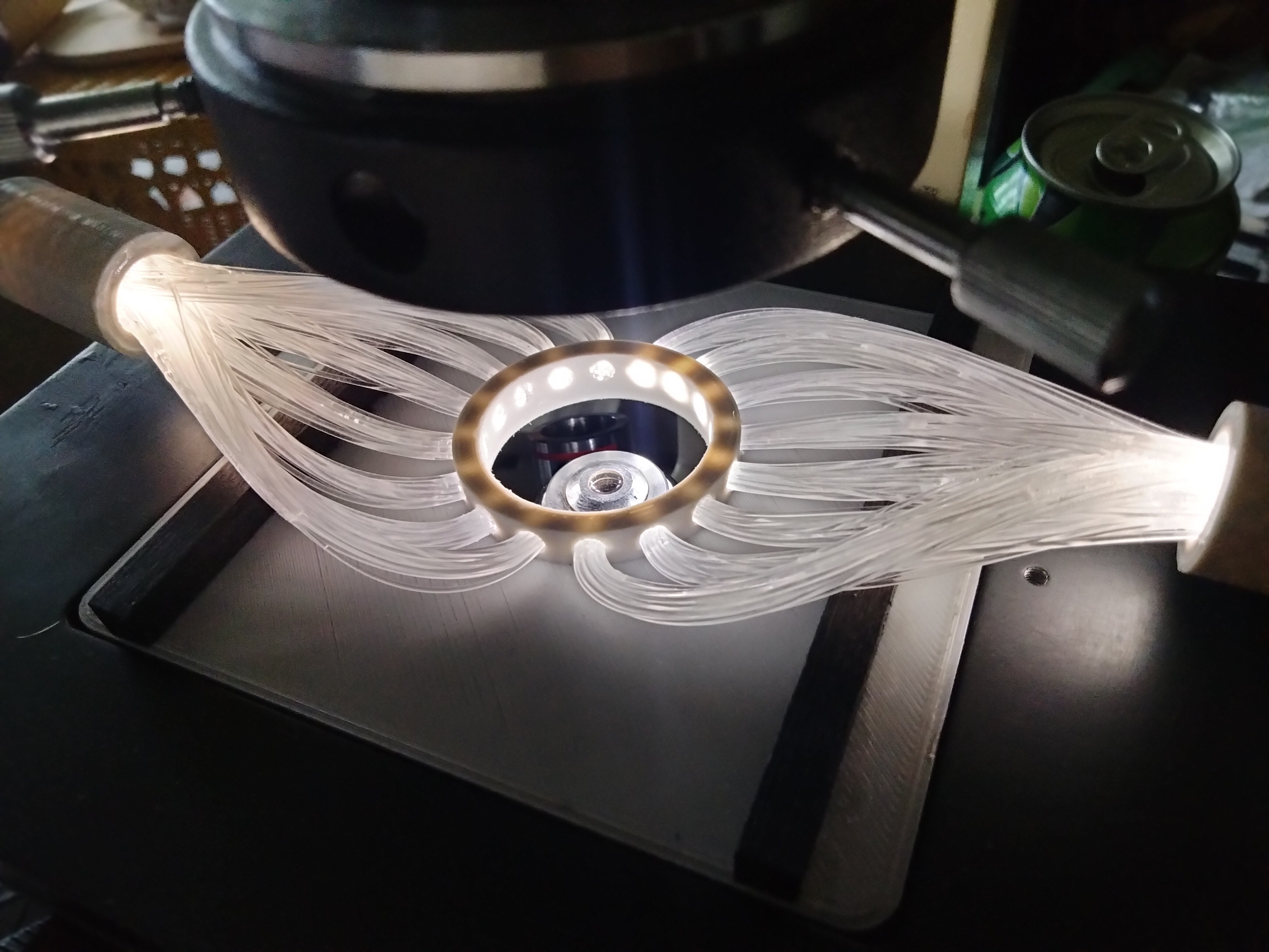
Just noticed I never showed how the actual fiber optics are being light up, I tried finding the smallest flashlights could and I think they work awesome. They were a tad expensive coming in at $14 a piece but they work very nice.
They are mounted in place using a drop of superglue and the end comes off so I can still change the batteries when that day comes. The fiber optics and flashlight are connected using a 3d printed tube. Luckily the diameter of the fiber optic bundle and the flashlight were the same which made the process very easy.
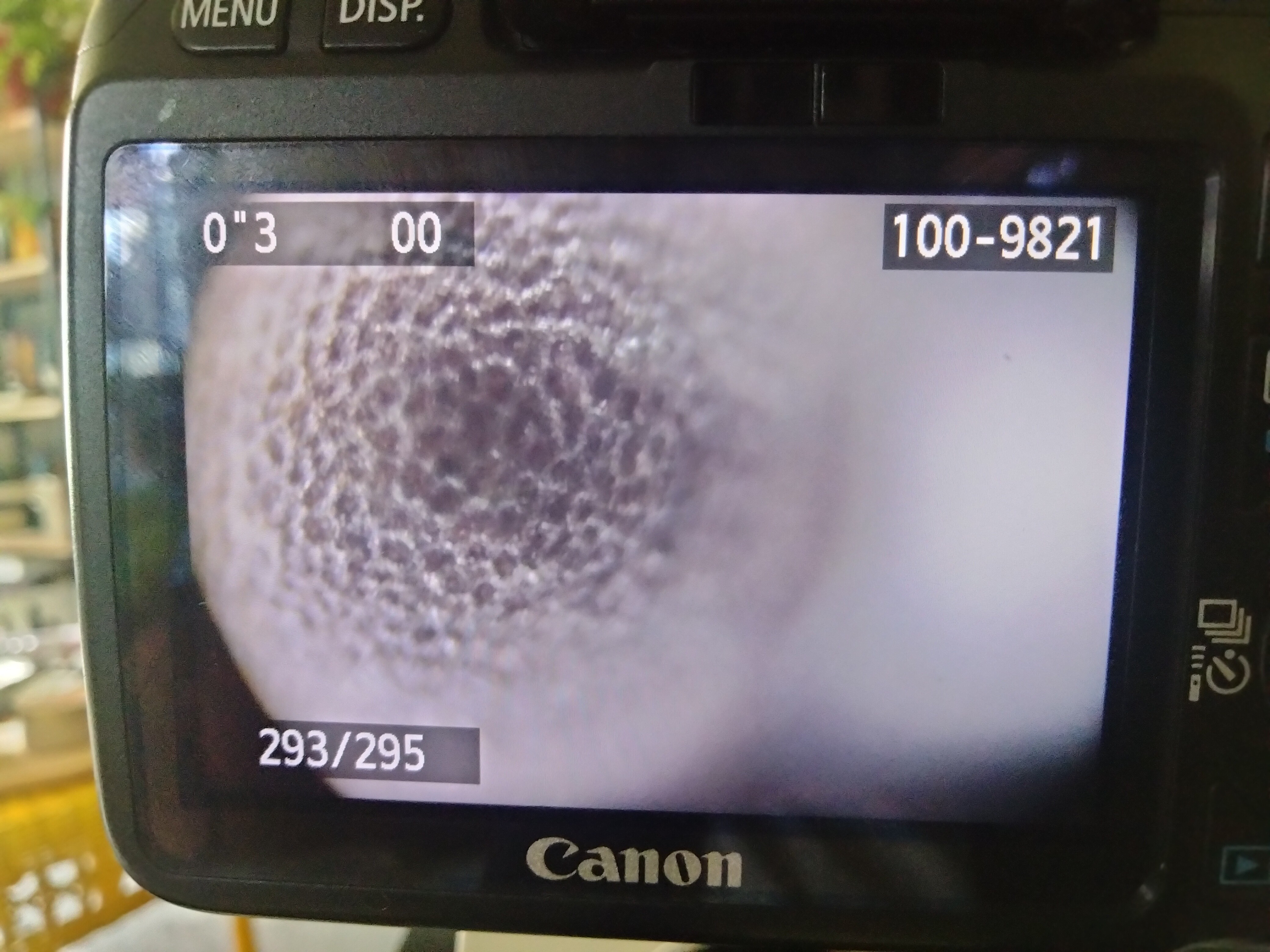
These were made using 5 different photos, The seed in the photo is the broccoli seed, I'm going to try a non-spherical seed to see if I can get better results. I'm still happy with the results and that I started with a difficult seed structure. More to come soon but I consider this project a success because of these results.
The software I used for the stacking was Picolay and if you are interested in Focus stacking, I would recommend checking it out, it's very easy to use and its open source and free.
Here are the photos that are going to be processed:
Here are the results :
The sample holder works perfect , still working on getting the photos done , it's taking a little bit longer to get the focus stacking working perfect but I'm hoping to have some to upload in the next few days. The seeds currently beings being examined are broccoli and pepper.
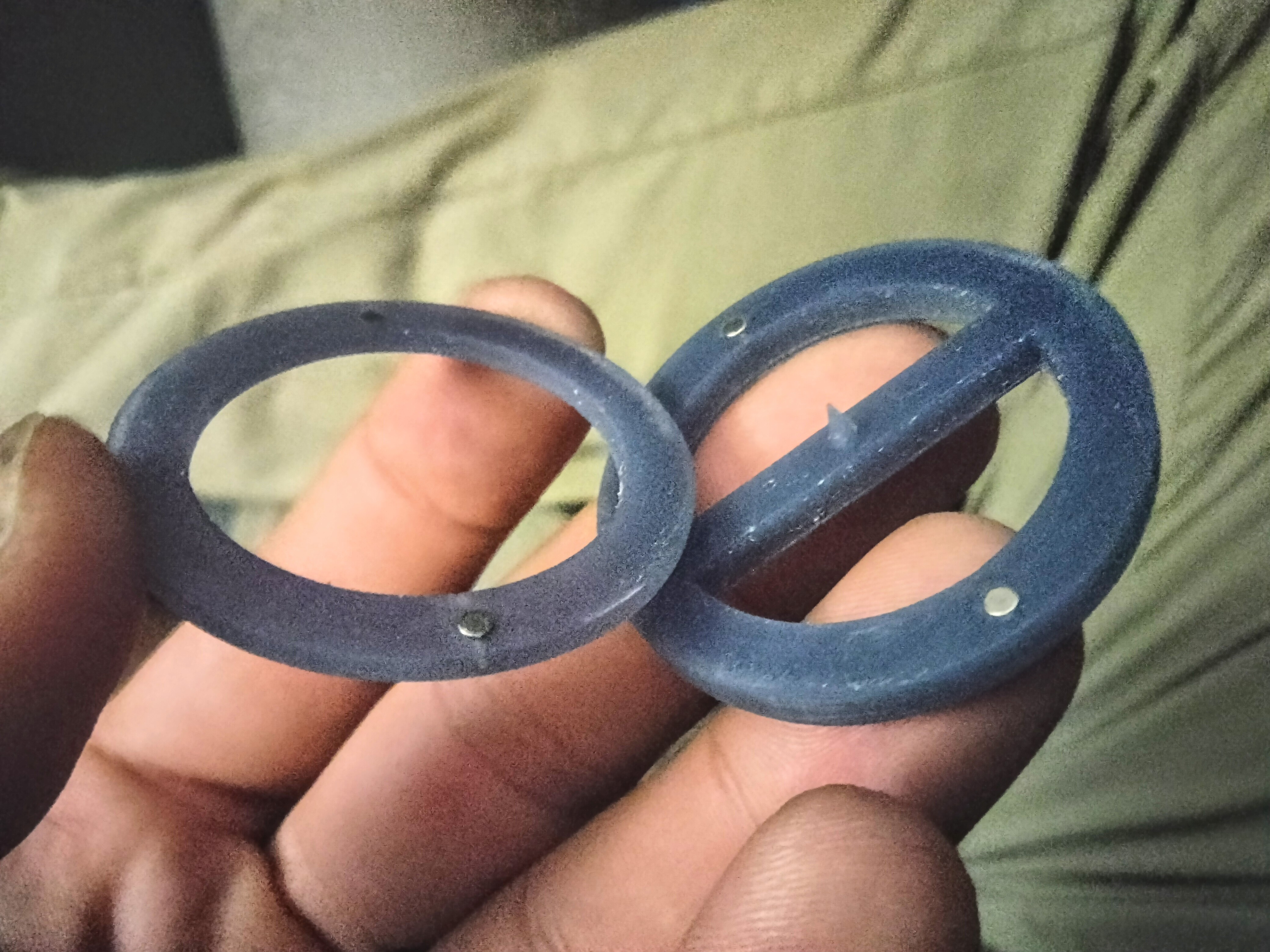
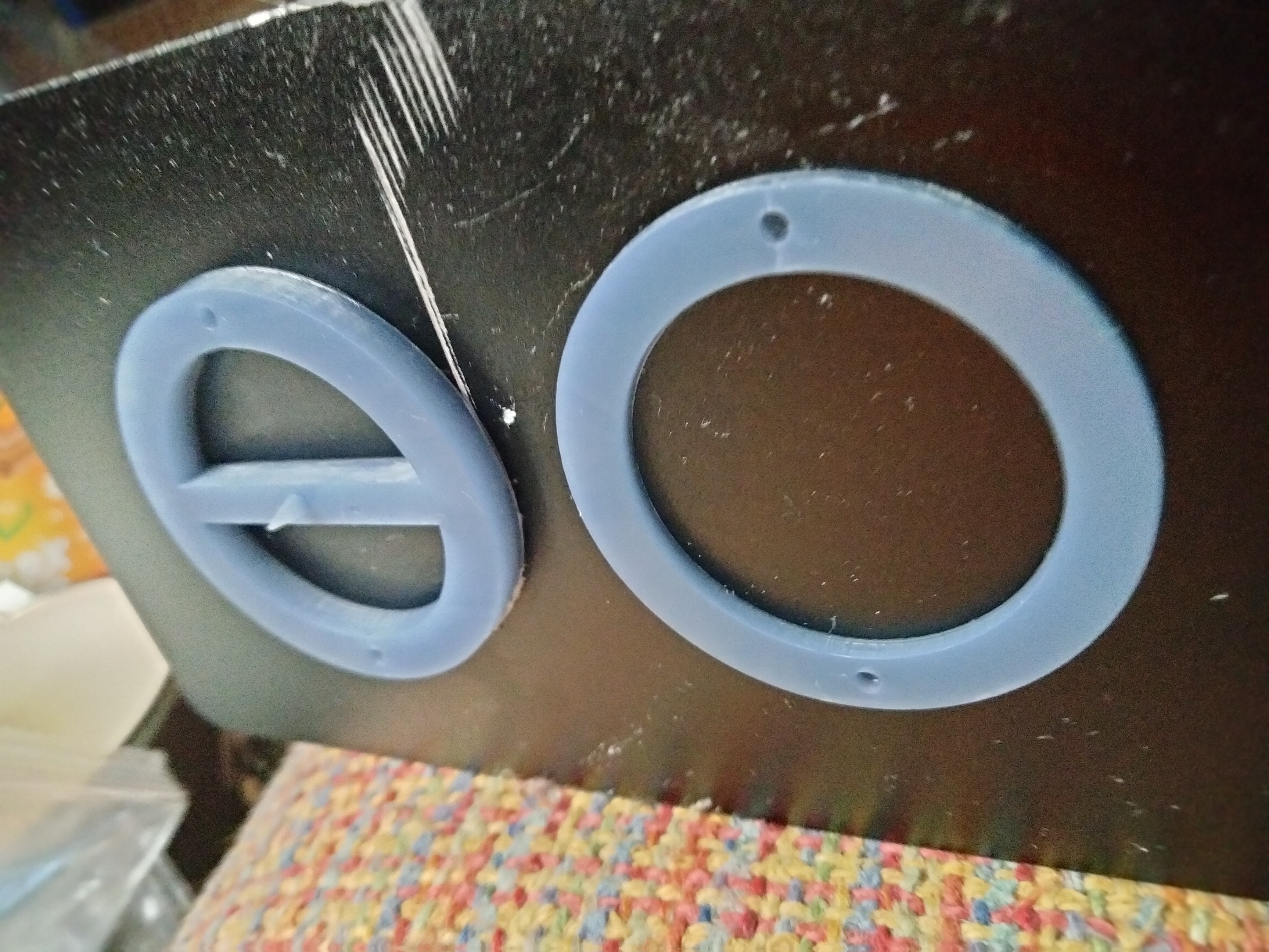
Finally got the resin prints all done and they came out perfect and the MAGNETS FIT!!!!!, now I just need to let them cure and get a sample mounted. I just wanted to post an update because I've been putting off this print because resin printers are smelly and I don't like stinking up my house but I finally pulled the trigger. With a little bit of luck I will have some cool macro photos and showing off the project at its fullest.
Finally got it all wired or lit up , now I just need to get the sample holder parts all printed and with a little bit of luck I should have them all done here soon. Manually holding the same seems to prove that the idea works but with a sample this small the smallest amount of movement loses the focus points.
Macro samples are usually to large to view on a slide or dish, which means you have to attach them to another object and then lower them into the focal space. The average size of samples that I will be viewing are around .3 to 3mm in size so I decided to design a magnetic sample holder that can be changed easily when changing samples . The sample will be attached to this with a small application of superglue, the amount of super glue necessary for this is smaller than the tip of a needle. The design on the right will be glued into place and the design on the left will be removable creating a magnetic hold. All of these parts are being printed on a resin printer to get the accuracy on the tip.
The magnets I will be using are 1*2mm
Solid view of the stack
X-ray view to show how the magnets will be aligned up.
The tips height was important to bring the sample into a position that would maximize light exposure. I was able to simulate this in Tinkercad.
Now I just need to get it all printed and the magnets should be here in a few days.
Alot was learned in the first version, the main lesson was the overall lighting degrees available while using fiber optics. This issue forced me to step away from positioning the fiber optics around the objectives and luckily my microscope uses drop in plates to fit different samples such as petri dishes or slides.
As with the first design I stuck with using Tinkercad , I mostly due this for simplicity and easy access computer to computer.
The print is about 100*106 an overall easy print for the Ender 3. From here it's goes straight into wiring all the fiber optics. Each hole has a diameter of 3mm which with a .75 mm fiber leads to 16 individual fibers per hole. I cut each of these to 6 inches long to allow for further trimming while progressing in the design.
Each fiber bundle is super glued into place on the inside and on the inside of 3mm hole. After a day of hardening the inner circle is sanded smooth and polished to allow the fiber to give off the brightest light possible. Turns out wiring and handling 256 pieces of fiber optics is not an easy task.
From here it came down to organizing and bringing each bundle to two large bundles of 128 fibers each. This wasn't an easy task but the method I choose was to wrap each bundle using heat shrink and zip ties, from here I would start hardening the bundles using super glue.
The heat shrink and zip ties were then cut off leaving me with two solid bundles which then were sanded to be flush and smooth. The final length to each bundle was about 4.5 inches.
From here I noticed one small design issue the light sources and the bundle ends are putting downward pressure on to the microscope. This normally wouldn't be a big deal but these plates aren't held down they simply sit into place. This downward pressure would remove the plate from it's position. This problem was easy to solve by raising the bundles up with a two pieces of square dowels. I should have built this into the original design but sometimes you just forget things either way easy fix.
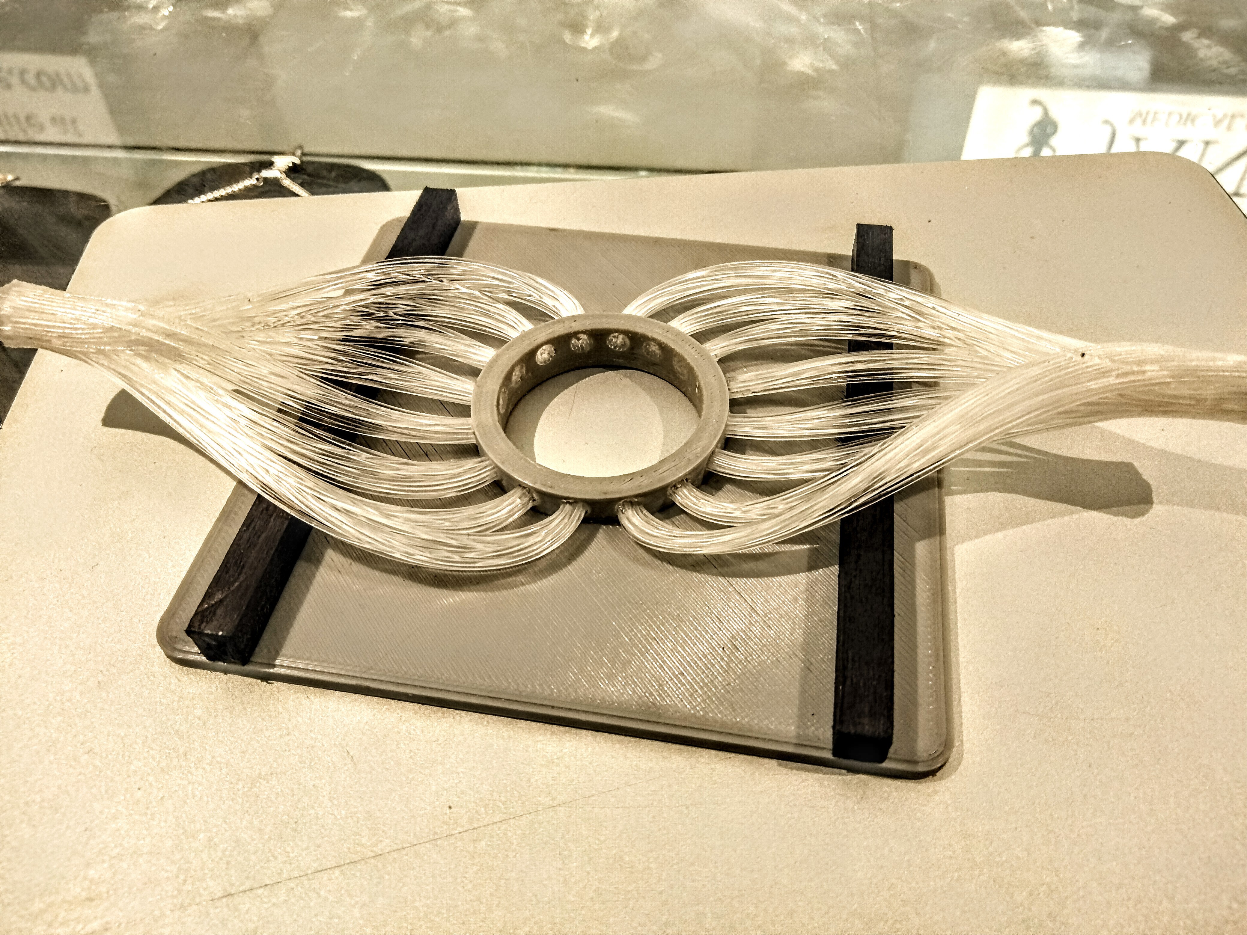
More updates to come soon just working on a way to hold the sample into place (I'm thinking magnets...tiny ones) and for the light sources to arrive.
Create an account to leave a comment. Already have an account? Log In.
To be honest it really isn't, I choose to use fiber optics to avoid soldering and developing a circuit. I wanted to use a alternative method of lighting because I've never used fiber optics before and wanted to see how it was to work with it. This design still uses LEDs in the two micro flashlights that provide light but I didn't have to wire them up so I was happy lol.
I didn't think about this at the time, but this setup is also alot more power saving then a LED system other than powering 16 Leds this is being done on 2. Now there is more things to take into account such as one's own time and my method of using fiber optics takes a lot more time.
i was looking in using those fibers for things ,recently too. and for your build the first thing i remembered was some of these fibers that illuminate on the side (the kind guys are putting into cars). seems so much more simple just make a circle with one thick of those , or take a regular one , make the circle and then sand the side for the light to come.
You could easily be right and that would have been a lot more simple, I just wanted to guarantee light exposure to the maximum and lets be honest a ton of fiber optics look cooler than just one wrapping around.
Become a member to follow this project and never miss any updates
 Jeremy Ruhland

 David Troetschel
 Benjamin Blundell
Why is the fiber optic solution better than a bunch of white LEDs surrounding the target?