The LRMS analog I/O board is intended for analog sensors or custom sensor designs that do not have digital interfaces. In addition to the analog I/O the board also supports I2C and TTL UART connections.
A high speed amplifier with a sample and hold peak detector with a DC boost converter has been included for photo detectors such as a silicon photo-multiplier.
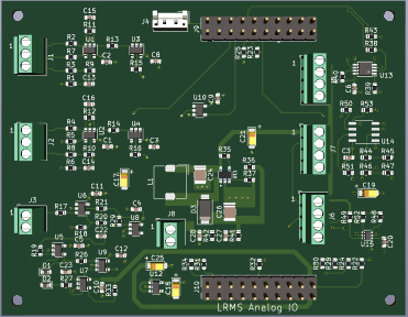
Board Connectors:
J1 & J2 : Two Configurable nano power operational amplifiers, can be configured as Differential, Single ended Non-Inverting/Inverting. Each amplifier output is buffered with a unity gain amplifier to the ADC channels.
(6Kz unity gain, 350nA per channel)
J3 : One high speed non-inverting operational amplifier with sample and hold peak detector.
(250Mhz unity gain, 100Mhz GBW)
J8: DC boost converter up to 32 volts DC.
J6 & J7 : I2C bus interface connectors
J5 : RS-232 TTL UART Connector
Discussions
Become a Hackaday.io Member
Create an account to leave a comment. Already have an account? Log In.