 Alvaro Barcellos
Jelly must have some external logic to complement FSM eeproms.
The way found to simulate an "IF" or "ELSE" was to change the "page", depending on external conditions.
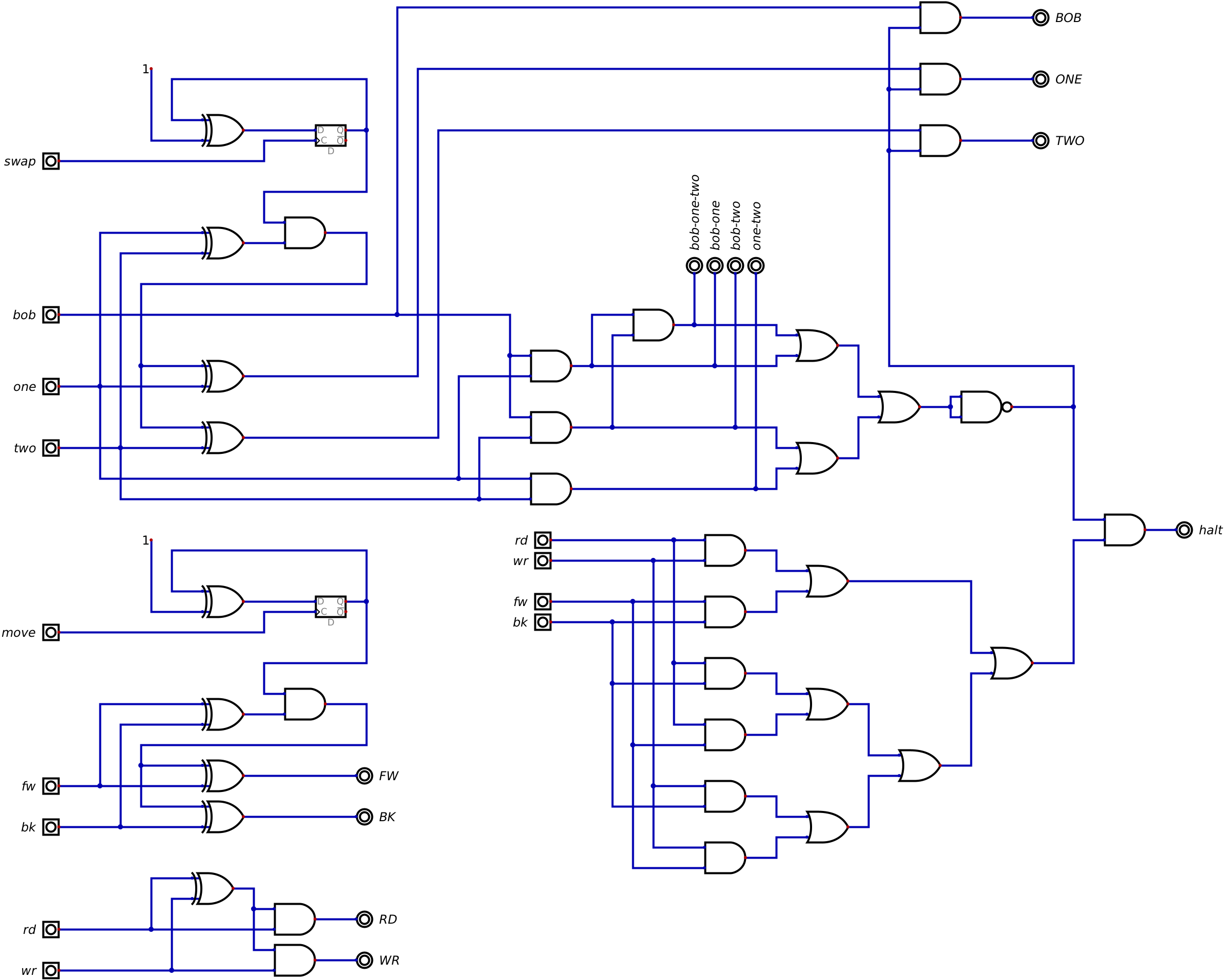
Circuits define "check and clear" logic. For bob, one, two signals, when two are active they are used to validate the conditions. For signals fw, bk, rd, wr, which cannot be active simultaneously.
The one and two signals are used to activate the swap signal, which works like a toggle switch that inverts the selection between one and two.
The bob and one signals are used to activate the move signal, which works like a toggle switch that inverts the selection between move forward or backward. This is needed to simplify the loop logic.
The bob and two signals are used with the zero signal to select "page one" by activating a toggle switch for address a08. In the "page one" commands just executes a next opcode, else [ and ], that increase or decrease a counter.
The pseudo code for processing [ and ] loops in "page one" :
for ( ; ; ) {
if (c==[) cnt++;
if (c==]) cnt--;
if (cnt == 0) break;
c = next();
}
PS.
the next action is a tape bob sequence of move and read. move could be forward or backward. the move signal toggles setup direction and both could be coded as a single operation move.
the logic circuit is showed in file jelly-two-halt.dig
-- this still a stub ---
the conditions table of loops [ and ] could be resumed as
| case | page | loop | condition | action |
| 1 | 0 | [ | zero == NO | next |
| 2 | 0 | [ | zero == YES | go page 1 |
| 3 | 1 | [ | zero == NO | inc count, next |
| 4 | 1 | [ | zero == YES | inc count, next |
| 5 | 0 | ] | zero == NO | go page 1 |
| 6 | 0 | ] | zero == YES | next |
| 7 | 1 | ] | zero == NO | dec count, prev |
| 8 | 1 | ] | zero == YES | go page 0 |
Discussions
Become a Hackaday.io Member
Create an account to leave a comment. Already have an account? Log In.