NicLamrlr
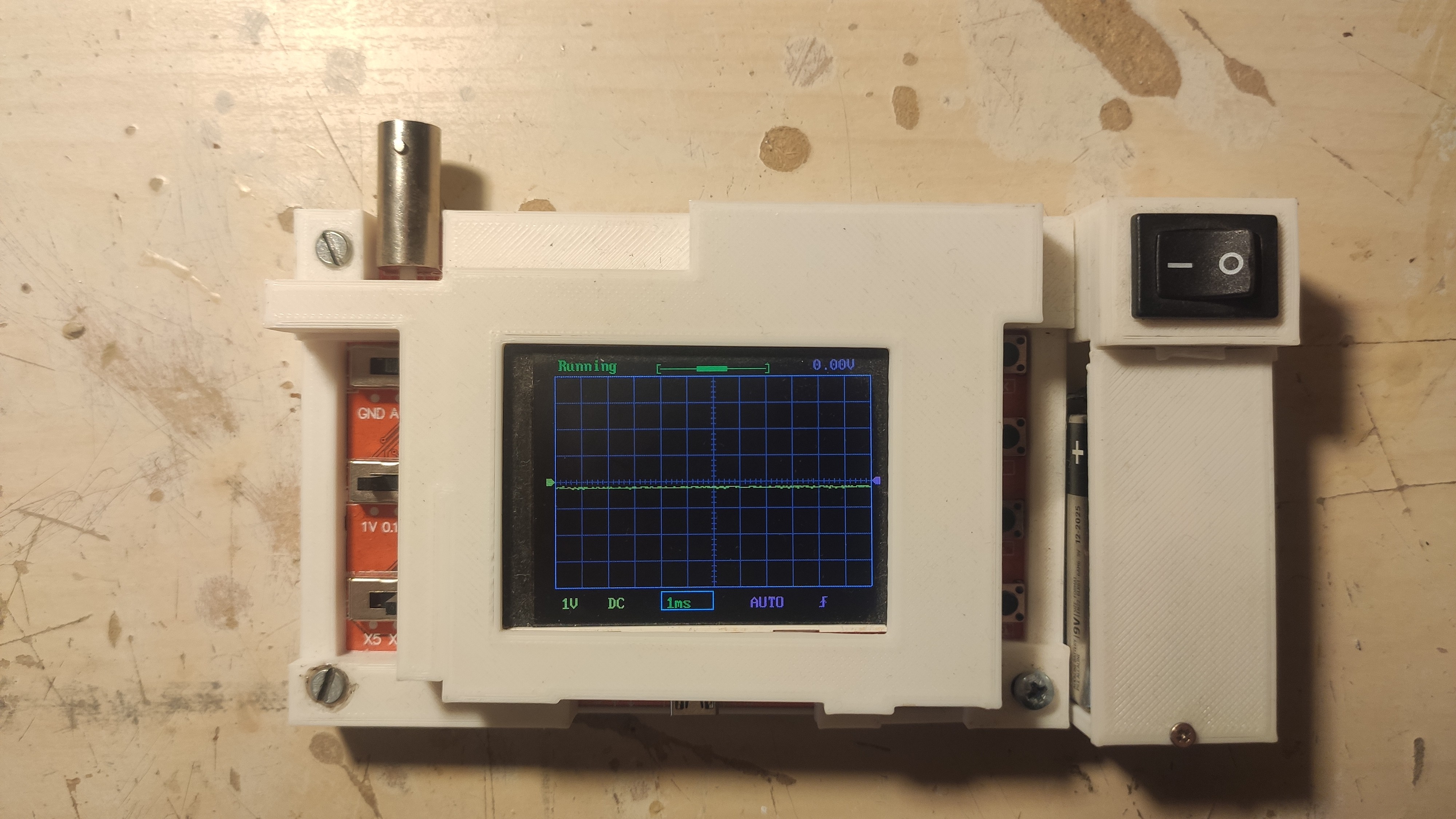
This is the first the first 3D design I developed for 3D printing, it turned out to be quite tricky since the PCB requires many irregular shapes to be able to fit and cover the components but it was a great learning experience.
0%
0%
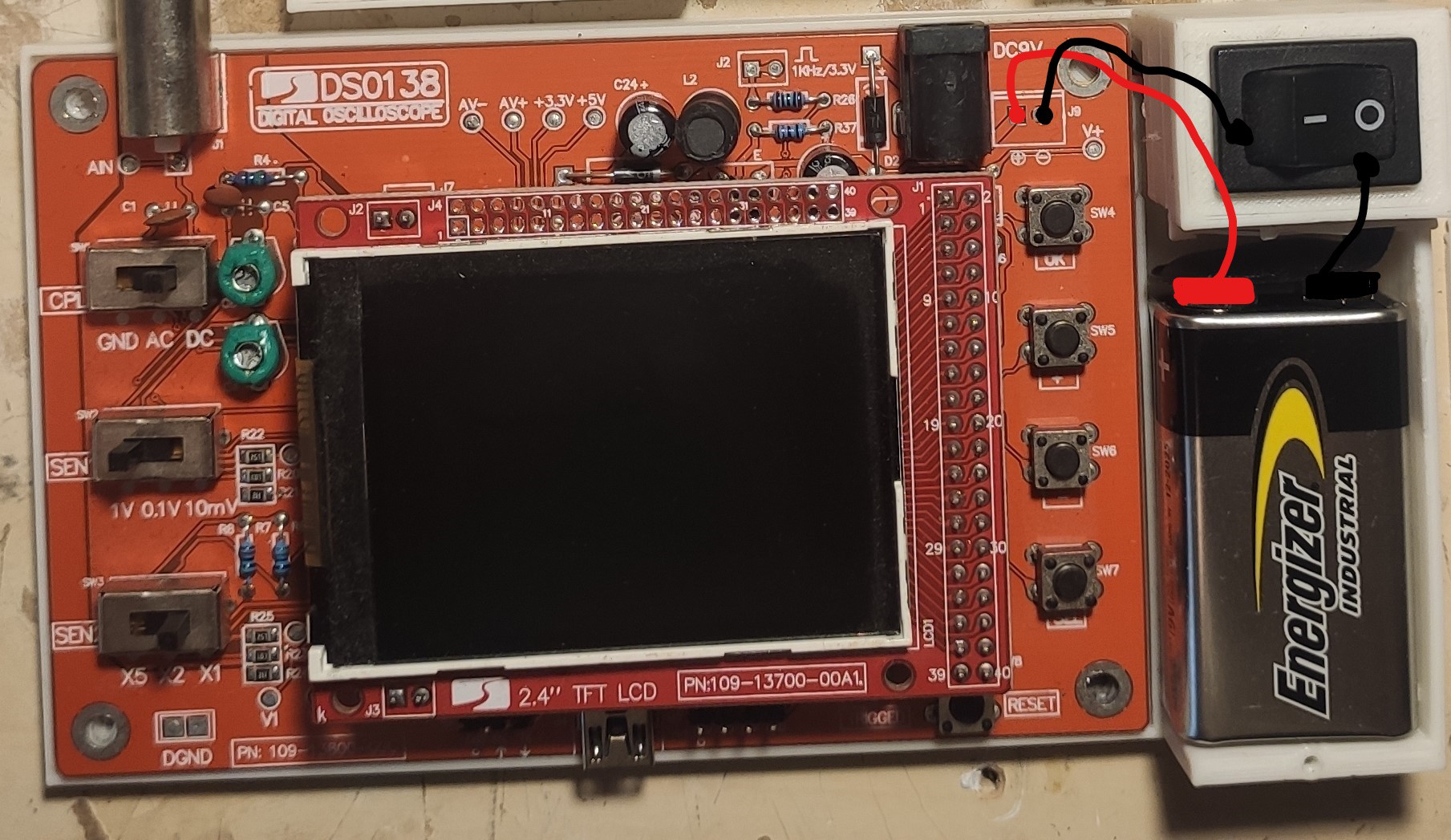
DSO138 Case and Battery
In this project we design a case for the DSO138 oscilloscope and make it battery powered
Become a Hackaday.io member
Already have an account? Log in.
Just one more thing
To make the experience fit your profile, pick a username and tell us what interests you.
Pick an awesome username
hackaday.io/
Your profile's URL: hackaday.io/username. Max 25 alphanumeric characters.
Pick a few interests
Projects that share your interests
People that share your interests