 StephanStrassleRojas
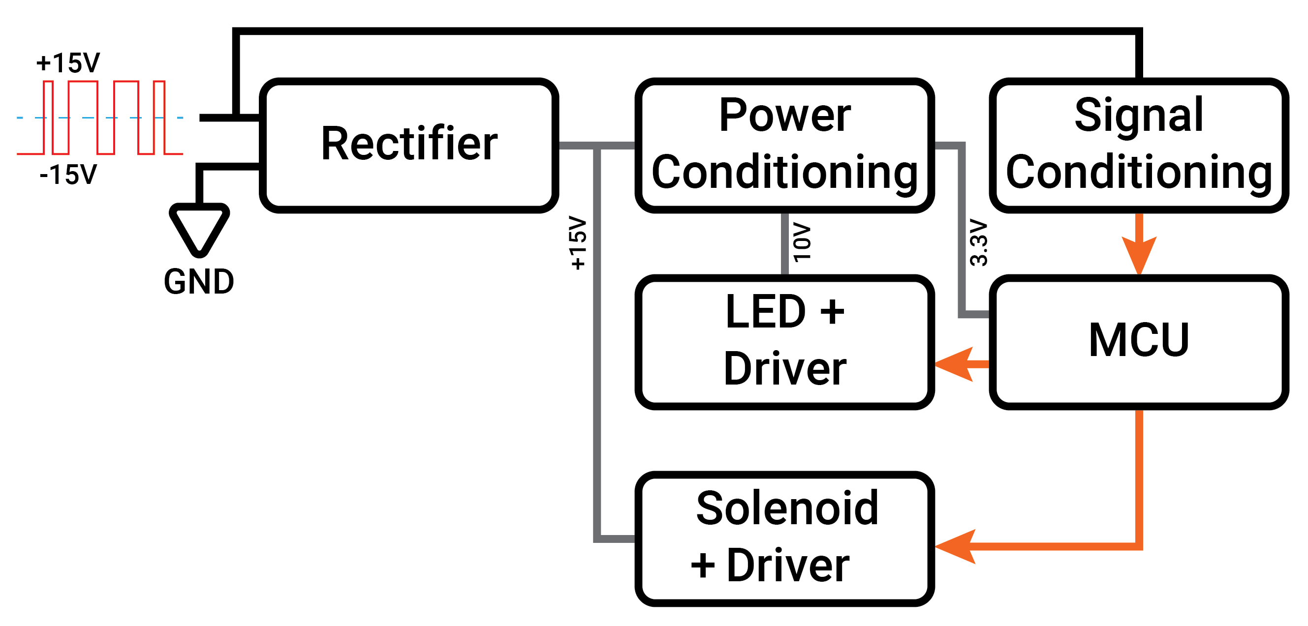
Rectifier Block: Rectifies the ±15V signal to generate a steady +15V source which can be used throughout the design
Power Conditioning Block: Takes the +15V source and generates a 3.3V and 10V linearly regulated source that is used to power other system components.
Signal conditioning Block: Taps directly onto the ±15V signal line and conditions it to produce an output that ranges from 0V to 3.3V, where a -15V results in a 0V and +15V results in 3.3V. This is used to generate a signal suitable for an MCU GPIO.
MCU Block: Contains an MCU that is used to interpret the Märklin Motorola protocol formatted data. The MCU generates digital outputs that are used to control the turnout solenoids as well as signaling LEDs.
LED + Driver Block: Contains bicolor LEDs that are powered by the 10V source, a transistor controlled by the MCU is used to switch the LEDs on and off using a 3.3V digital signal.
Solenoid + Driver: Contains a dual solenoid driver, which is controlled by 3.3V digital signal generated by the MCU. The dual driver setup allows for single, three-way, and crossover turnouts to be controlled by a single board.
Discussions
Become a Hackaday.io Member
Create an account to leave a comment. Already have an account? Log In.