 WJCarpenter
I made the decision to revise the PCB again, to correct one definite (non-fatal) mistake and another arguable mistake. At the same time, I made a number of smaller changes in the name of "design for manufacturability" (DFM). In this case, the "manufacturer" is mostly me. If someone else builds some of these, they will also probably be a hobbyist. They'll be sourcing parts in small quantities, maybe taking what they can find or using what they have on hand. They'll be doing assembly in a dungeon-like work area that doesn't want to have computer equipment and lots of paperwork strewn about. OK, I'm really talking about me.
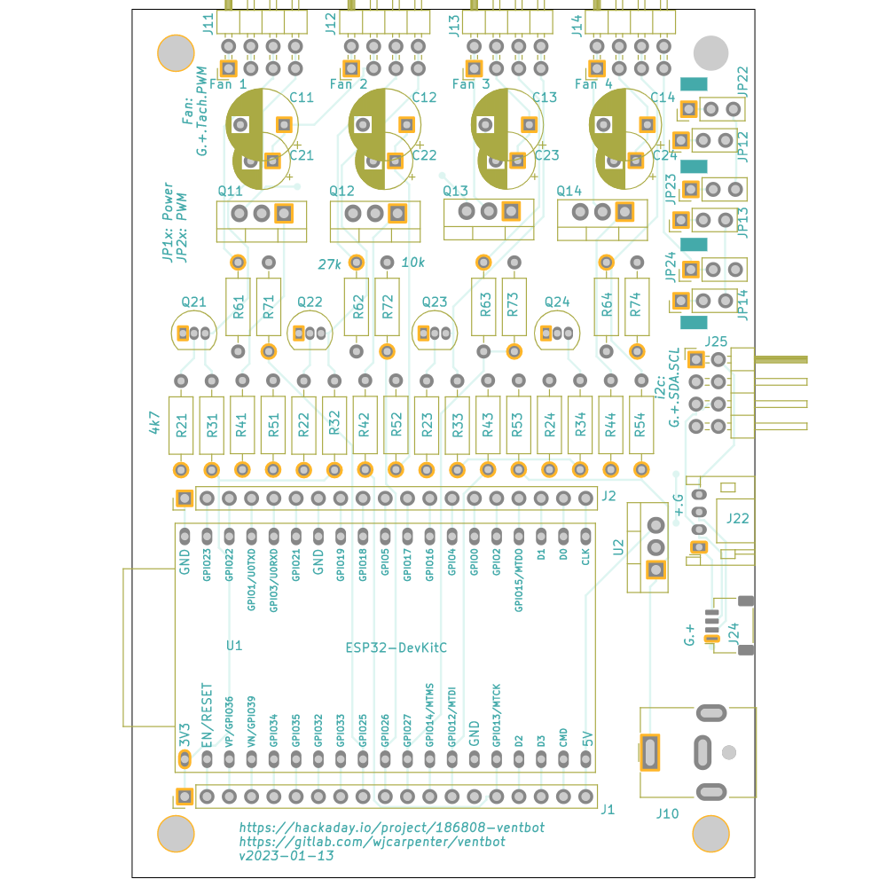
Here are the changes I made:
- Added the footprint for the 7805 (U2). I placed it so it wouldn't block the USB connector on the ESP32 module. There should still be enough room for the 7805 to "lean back" a bit if it doesn't need a heatsink.
- Corrected the pin ordering for the JST-PH connector (J22). This was backwards in the first two iterations of the board, so you couldn't directly use it with STEMMA or Grove components. I added a bit of marking on the silkscreen so that it's clear which pin is which for the wiring for it and the JST-SH (J24) connector.
- I changed the footprint of the other I2C connector (J25) from two separate (but conveniently spaced) 1x4 pin headers to a single 2x4 right angle pin header. That makes it more obvious what's going on, and someone could still use separate straight-through pin headers if they wanted to.
- Along the same lines, I changed the footprints of the fan connectors (J11, J12, J13, J14) to be those same 2x4 right-angle pin headers. To use those, you have to snip off the bottom row of horizontal pins, but the pad spacing and physical dimensions are otherwise compatible with the official friction-fit fan connectors. Someone could still choose to use either vertical insertion or right-angle versions of those.
- For the power and PWM option jumpers (JP12, JP13, JP14, JP22, JP23, JP24), I have previously populated boards both ways: with a 3-pin header and jumpers, and with wires soldered across pins 1-2. Given that the choice will almost always be connecting pins 1-2 for all six options, I wanted to simplify that for the common case. I left the footprint as a 3-pin header, but I put a trace between pins 1-2 on the front of the board for all six options. If someone wants to select pins 2-3, they can cut that trace and then join pins 2-3 with either a jumper or a soldered wire.
- I added some text to the silkscreen as a reminder of which option jumpers control power sharing and which control PWM sharing. Unfortunately, there wasn't room near those footprints, so it's all the way across the board. Tolerable.
- Most of the resistor values were not critical. I changed the 100 ohm current limiting resistors to 4.7k ohms. That reduced the number of distinct resistor values from 4 to 3.
- One of the resistor values was 27.4k ohms. I had copied that value from a reference design. 27.4k is not a standard value, and I had been using 27k when assembling boards. I formalized that by changing the design to 27k ohms.
- I moved some resistor placements around so that the one long row of resistors is now all 4.7k values. That should eliminate some opportunities for making a mistake. That made the R1x resistors appear out of sequence, so I changes their references to the previously unused R4x series.
- I added reminders of values for the various resistors on the silkscreen. That matters most for the two values that are not 4.7k.
- The redone trace routing conveniently allowed me to extend all the way to the edge of the PCB the keepout area for the ESP32 antenna position. I still don't know how much difference that makes, but I have done my duty.
- I added a redundant footprint for the capacitors. The second footprint has a closer lead spacing, which I think is more common these days. Depending on the capacitors you actually have, you can pick whichever footprint gives the best physical fit.
Discussions
Become a Hackaday.io Member
Create an account to leave a comment. Already have an account? Log In.