WJCarpenter
-
Ramp up and down
11/20/2022 at 21:40 • 0 commentsI plan to have a configurable way to spin the fans up and down when needed. When I say configurable, I currently don't have in mind anything fancier than editing some tabular data in the ESPHome configuration file. Maybe someday that table will be stored in ESP32 preferences storage so it can be modified without rebuilding the firmware. That's a bigger adventure than I am thinking about at the moment. I'm imagining the ESPHome configuration file being edited by someone who is not necessarily technically sophisticated. So, I don't want them to have to dig around too much in the file or have to deal with syntax that is too complex.
Here is what I have right now:
- The ramp consists of any number of steps. Presumably, they start with low speeds and move increasingly upwards, but that is not enforced.
- There's a kind of implied first step, which is "everything is off".
- Each step consists of a duration (I'm not sure yet if it will be in seconds or milliseconds) and a set of PWM duty cycle percentages. The meaning is "set the fans to the specified PWM duty cycle values and wait for the duration time before moving to the next step".
- The duration for the final step is ignored (or treated as "infinity") since there is nothing to wait for. The fans will continue at those settings until it's time to ramp down.
- For ramp down, the steps are used in the reverse order. The highest-numbered step will ordinarily be where the ramp up left us. For ramp down, the duration of that step is taken as 0.
I'm not completely sure the ramp up and ramp down behavior should be symmetric. I'm doing that for simplicity but may have to add more complexity to it later.
ESPHome has a feature for defining global variables. Theoretically, the ramp up and ramp down could be done completely using the table defined in global variables and ESPHome primitives. It's rather inconvenient to do that for more than a few simple variables, and I think it would obscure the logic of the simple table I'm using. I'm planning to use an ESPHome lambda block to do the ramp up and ramp down in C++.
To avoid the need to naive users to grovel around in C++ code located deep in the ESPHome configuration file, I'm using the ESPHome substitutions feature to define the guts of the table up near the top of the ESPHome configuration file. That fragment is then plugged into some C++ code in an ESPHome lambda later. It's a purely mechanical substitution. Here is an example of the table. The numbers in this example are not sensible and were chosen just to be sure of what's going on in debug logging.
substitutions:
  RAMP_TABLE: |-
    {1, {11, 12, 13, 14}},
    {2, {21, 22, 23}},
    {3, {31, 32}},
    {4, {41}},
The syntax here is not too onerous, and I think the average person can handle it.
It's still possible to get it wrong. When you're trying to do a static initialization of an array of structs in C++, it's like trying to get help from a lawyer with whom you do not share a common language. You say what you think you want, and they respond with a load of gibberish. There are a few words in there that you recognize, but the sequence of words makes no sense and is not helpful. With the aid of some web searches, you eventually get something that does not bring forth a string of complaints from them, but you're not sure what you asked for is what you want. (I spent a lot of years doing development in C. I was at Bell Labs when C++ came along. For a while, the motto was "a better C", but it eventually changed to "a better C, plus a couple of train wrecks thrown in for free".)
Here is some ESPHome lambda code that prints out the ramp table. You can see the ${RAMP_TABLE} value substituted at around line 7. ${FAN_COUNT} is another ESPHome substitution and has the value 4 (for the maximum possible fans, not necessarily the number of actual fans).
      - lambda: |-
          typedef struct {
            short duration;
            short pwm[${FAN_COUNT}];
          } RAMP_STEP;
          static RAMP_STEP ramp_steps[] = {
            ${RAMP_TABLE}
          };
          static short number_of_ramp_steps = sizeof(ramp_steps) / sizeof(ramp_steps[0]);
          static bool going_up;
          going_up = !going_up;
          ESP_LOGD("main", "There are %d ramp step", number_of_ramp_steps);
          for (int ss=0; ss<number_of_ramp_steps; ++ss) {
            RAMP_STEP *ramp_step = going_up ? &(ramp_steps[ss]) : &(ramp_steps[${FAN_COUNT} - ss - 1]);
            ESP_LOGD("main", "%s step %d, dur %d", going_up?"UP  ":"DOWN", ss, ramp_step->duration);
            for (int ppu=0; ppu<${FAN_COUNT}; ++ppu) {
              ESP_LOGD("main", "  pwm %d", ramp_step->pwm[ppu]);
            }
          }
Missing values in the ramp table are initialized to 0. That's convenient for anyone who has fewer than 4 fans. I'm not sure yet what I will do during ramp up and ramp down when I see a 0 value. It might mean turn the fan off, or it might mean "don't change from the previous step's value". That's for another day.
Here's the ESPHome debug log output from the lambda block after one ramp up and one ramp down:
[13:37:31][D][main:077]: There are 4 ramp step [13:37:31][D][main:080]: UP step 0, dur 1 [13:37:31][D][main:082]: pwm 11 [13:37:31][D][main:082]: pwm 12 [13:37:31][D][main:082]: pwm 13 [13:37:31][D][main:082]: pwm 14 [13:37:31][D][main:080]: UP step 1, dur 2 [13:37:31][D][main:082]: pwm 21 [13:37:31][D][main:082]: pwm 22 [13:37:31][D][main:082]: pwm 23 [13:37:31][D][main:082]: pwm 0 [13:37:31][D][main:080]: UP step 2, dur 3 [13:37:31][D][main:082]: pwm 31 [13:37:31][D][main:082]: pwm 32 [13:37:31][D][main:082]: pwm 0 [13:37:31][D][main:082]: pwm 0 [13:37:31][D][main:080]: UP step 3, dur 4 [13:37:31][D][main:082]: pwm 41 [13:37:31][D][main:082]: pwm 0 [13:37:31][D][main:082]: pwm 0 [13:37:31][D][main:082]: pwm 0 [13:37:36][D][main:077]: There are 4 ramp step [13:37:36][D][main:080]: DOWN step 0, dur 4 [13:37:36][D][main:082]: pwm 41 [13:37:36][D][main:082]: pwm 0 [13:37:36][D][main:082]: pwm 0 [13:37:36][D][main:082]: pwm 0 [13:37:36][D][main:080]: DOWN step 1, dur 3 [13:37:36][D][main:082]: pwm 31 [13:37:36][D][main:082]: pwm 32 [13:37:36][D][main:082]: pwm 0 [13:37:36][D][main:082]: pwm 0 [13:37:36][D][main:080]: DOWN step 2, dur 2 [13:37:36][D][main:082]: pwm 21 [13:37:36][D][main:082]: pwm 22 [13:37:36][D][main:082]: pwm 23 [13:37:36][D][main:082]: pwm 0 [13:37:36][D][main:080]: DOWN step 3, dur 1 [13:37:36][D][main:082]: pwm 11 [13:37:36][D][main:082]: pwm 12 [13:37:36][D][main:082]: pwm 13 [13:37:36][D][main:082]: pwm 14 -
Design thoughts snapshot
11/20/2022 at 20:12 • 0 commentsThis is a recap of my thinking about the design of this project. Some of it I've mentioned or hinted in earlier project logs, and some has lived only in my tiny brain.
- For the software framework, I plan to use ESPHome. I've used that already for several projects. Except for the aggravations inherent in YAML, it's very easy to work with, and it's very reliable. ESPHome will take care of a lot of plumbing work (WiFi, sensor readings, and more) so I don't have to worry about it.
- Using ESPHome makes it very simple to hook into my Home Assistant server. I'm not sure yet what I want to do via Home Assistant. I know I don't want to make it a "must have" part of the system, but there are lots of "nice to have" possibilities.
- The microcontroller in the project will be a 38-pin ESP32-DevKitC. It's arguably overkill for this design, but it has plenty of available GPIO pins for what I want to do. They are widely available for US$10-15 or so. It has several kinds of communications capabilities to give me some flexibility for as-yet-unplanned user interface possibilities.
- Although I'm using "quiet" fans, they could still be startling when they switch on in a quiet bedroom in the dead of night. Fan noise itself, at low levels, is not disturbing. It's the sudden change from silence to something audible that pokes our sleeping brains. To ease the transition, I plan to ramp up the fan speeds from dead stop to my target speed. When turning them off, I'll also ramp back down. I'll have a later project log about this ramping.
I've started working on a schematic and PCB layout to hold all this. It provided me a chance to finally try out KiCad (which is going pretty well; the Freerouting plugin has already saved me hours and hours of time). Even with all the stuff I'm about to describe, it all fits onto a double-side board that is less than 75 mm square. Partly for philosophical reasons and partly for practical reasons, I'm designing some flexibility options into the PCB. I'm only planning to make at most 4-5 of these devices, but the PCB fabrication places generally include 10 copies of the board. When ordering from Asia, shipping is a non-trivial percentage of the cost of getting the boards in your hands, so I might order more than 10 copies once I'm confident in my PCB design. It will be nice to have other uses for them. My experience with the PCB prototyping services is that the boards are pretty darned nice.
- For my house, I'll be using three 92 mm fans. I have enough ESP32 pins available, so the board allows for four fans. I'm planning some software help to automatically detect which of the four fans is actually present at boot-up. Things will probably work OK if 3-pin non-PWM fans are used, though some of the beauty of the overall design will be lost.
- Fan #1 must always be present, but all other fan positions are optional. I plan to control all the fans individually, but there are jumpers on the board so that everything (well, PVM control lines and power) can be wired to be controlled by whatever happens to Fan #1.
- Most fans do not turn off completely, even at 0% PWM duty cycle. I plan to handle that by controlling the 12v supply to the fan with a MOSFET. The particular part I'm using is something I had used in a previous project, and I still had a couple on-hand. It's N-Channel, which to my non-EE brain is slightly confusing because you end up switching the "ground supply" to the device. Yeah, yeah, I know it works, and I prototyped it on a breadboard to make sure I got it right. It will be possible to omit the MOSFETs and use a wire jumper between pads to always have power supplied to the fans.
- There are current-limiting resistors on the signal going to the MOSFET Gate. I'm not really sure they are needed. If not, they can be replaced with wire jumpers.
- The temperature sensor, which controls when the fans need to turn on or turn off, will be off-board but connected via I2C. Since I2C devices can chain together using exactly the same 4 wires, I'm putting some extra connectors on the PCB for additional I2C devices. In addition to standard 100 mil (2.54 mm) pin headers, I'm also putting pads for JST PH 2 mm pitch and JST SH 1 mm pitch 4-pin connectors (which are compatible with Adafruit's original STEMMA and STEMMA QT, SparkFun's QWIIC, and Seeed's Grove). I don't have any specific plans for those extra connectors and might not even populate them on the boards I build, but it's easy to put the pads on the PCB.
- There are some pins on the ESP32 not used in this design. For that, and for possible re-purposing of extra boards, I've put down pads for a strip of pin headers on both sides of the ESP32 to give easy access to everything.
- The ESP32 will be powered by the same 12v input that powers the fans. I originally thought I could step that down to 7v or so with a resistor divider. When I tried that it and it didn't work, I found out that it was just another case of my ignorance of EE fundamentals, and it was never going to work. The ESP32 handles the 12v input on the 5v pin without much hardship. I've run it that way for hours and the components only get mildly warm. I'm leaving the pads in place for the resistor network. To directly use the 12v supply, a jumper will replace one of the resistors. If the voltage going to the ESP32 needs to be stepped down, the pads can be used to intercept the power and condition it with something.
-
The fan blink
11/20/2022 at 00:08 • 0 commentsTo test my idea of controlling the power to the fan via the MOSFET, I wired up a fan on the breadboard to be controlled by the MOSFET, similar to how I wired up the LED to blink for an earlier project log. (It's a Noctua NF-B9 redux-1600 PWM. For this test, it doesn't have a PWM input and so it runs at full speed.) I kept the LED (with a source voltage coming from the 3.3v output of the ESP32) as a visual reference. I changed the on/off interval from half a second to 5 seconds to give the fan time to come up to speed. The fan is powered by a 12v input (as is the ESP32, come to think of it).
-
Temperature rises
11/19/2022 at 23:14 • 0 commentsNow that it's autumn in my area, and the temperatures are frequently in the 30-40 F range, I can see how things look in my vents when the heat is on. This is analogous to the measurements I made in the summer when my heat pump was in cooling mode.
I returned the temperature sensor to the same vent and monitored it for a few hours. Here is that history graphed:
![]()
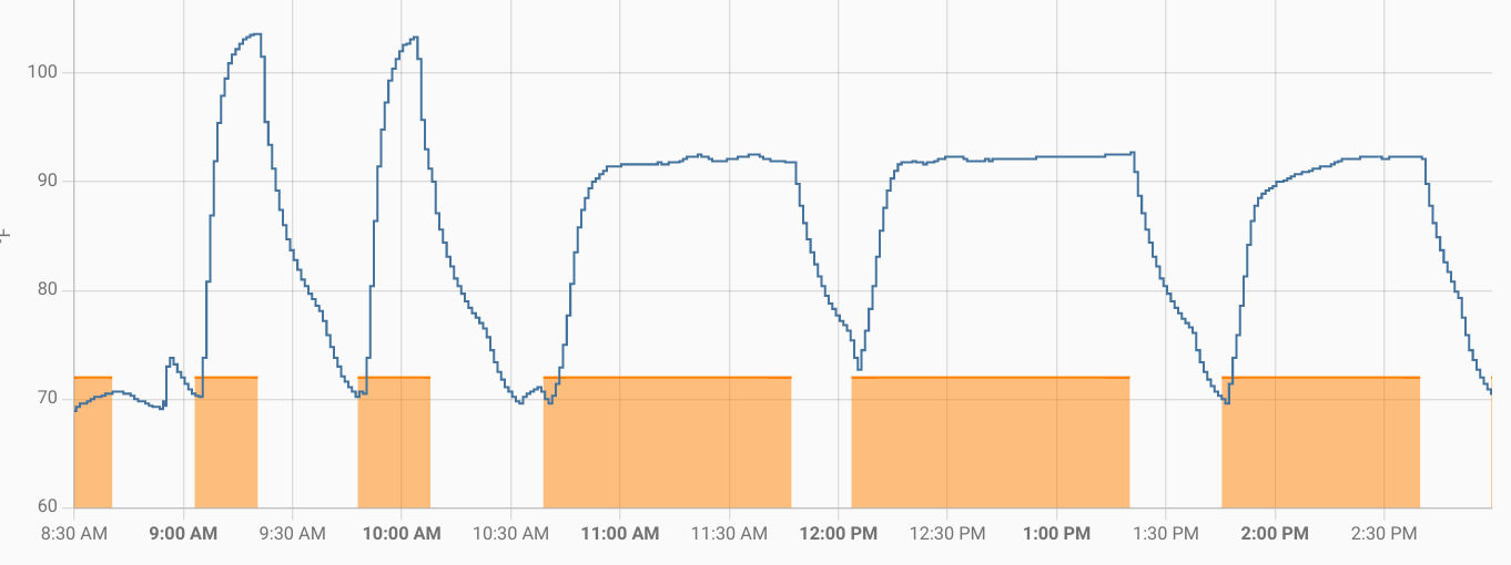
The yellow-ish/orange-ish blocks are when the heat was on. As hoped, it corresponds nicely to the large rise in temperature inside the vent opening. By eyeball, if I use about 85 F as a trigger point, it's a 5-10 minute delay from the heat coming on to reaching that trigger point, and there is something similar when the heat turns off. Based on the summer measurements, I was thinking something like 60 F for the cool trigger. Because of different duct lengths, some of the other rooms might have different high and low temperature triggers. I'll make that configurable.
A couple of the morning heat cycles were short in duration and rose quite a bit higher than the later, longer cycles. During those shorter, hotter cycles, my gas furnace was providing auxiliary heat. The longer, not-as-hot cycles were the heat pump living up to its name and pumping heat from the outside into my house.
-
On the blink
11/19/2022 at 04:35 • 0 commentsSince I plan to use MOSFETs to turn the power to the fans off and on, I wanted to make sure I understood how that should be wired up. I wrote the equivalent of the ubiquitous "blink" program in ESPHome configuration.
substitutions: node_name: esp32-blink log_level: DEBUG wifi_ssid: !secret wifi_ssid wifi_password: !secret wifi_password ota_password: !secret ota_password LED: 'GPIO14' esphome: name: ${node_name} platform: esp32 board: esp32dev wifi: ssid: ${wifi_ssid} password: ${wifi_password} ota: password: ${ota_password} switch: - platform: gpio name: "${node_name} LED" id: i_led internal: true pin: number: ${LED} inverted: yes interval: - interval: 0.5s then: - switch.toggle: i_led- GPIO14 is the control signal. It's wired to the Gate of the MOSFET. Because I've seen it illustrated a couple of places, I also used a resistor for current limiting.
- The MOSFET Source is wired to one of the ground pins of the ESP32.
- The MOSFET Drain is wired through a current limiting resistor to the cathode leg of an LED.
- The anode leg of the LED is wired directly to the 3.3v output pin of the ESP32.
- The ESPHome configuration toggles the GPIO14 control signal every 0.5 seconds.
-
Wandering tachometer, a digression
09/11/2022 at 21:32 • 0 comments[Edit, 2 October 2022: OK, forget all that. I set everything up on my breadboard a second time, and everything came out nice, well-behaved square waves. I'm not sure what I did wrong the first time, but I suspect that I didn't correctly set up the pull-up resistor on the fan tach output, even though that was my intention. Since the fans all seem to tolerate the EPS32's 3.3v PWM signal and since the tachometer output is now nicely cycling between ground and 3.3v, I can probably get away with directly connecting things instead of using a signal switching transistor.]
On the way to measuring the loudness of fans running at various speeds, I also wired up the tachometer output to an ESP32 pin to monitor the speed. The somewhat ancient Intel spec for PWM fans (I haven't yet found a newer one) requires a linear relationship between the PWM duty cycle and the fan RPMs, at least for the mainstream part of the graph. The spec generally asks things to meet a +/-10% tolerance. I wanted to see if that actually held true for the PWM fans I have on hand.
The tachometer output from the fan is the 3rd wire on the connector, for both 3-wire (non-PWM) and 4-wire (PWM) fans. It's called "sense" in some diagrams and documentation. The idea is that the controller can get feedback about the effects of the inputs it sends to the fan (whether PWM duty cycle or varying supply voltage) and can dial in some particular RPM target, or at least display the fan speed for humans to geek out on. The spec calls for 2 pulses per revolution, typically implemented via Hall effect sensors. The pulse count divided in half and then multiplied by 60 will give RPMs. (Puzzler for wiseguys: see if you can solve that with just a single multiplication.)
Like many explorers before me, I found the pulse count measurements to be surprisingly unstable. As I changed the PWM duty cycle in increments of 10%, I could hear the fans running faster. But it took a couple of minutes for the pulse counts to settle down, and they never really became completely stable. There was generally a correlation between the PWM duty cycle and the RPMs, but it was only roughly linear. Most perplexing of all, when I got up to the 80-100% duty cycle area, the pulse counts sometimes decreased pretty dramatically.
At first, I blamed the fan manufacturer, but I observed this on five different fans from three manufacturers. What the heck could be going on? The mystery was at least partially resolved when I used a scope to observe the tachometer output. I was slightly surprised by one thing and greatly surprised by another.
![]()
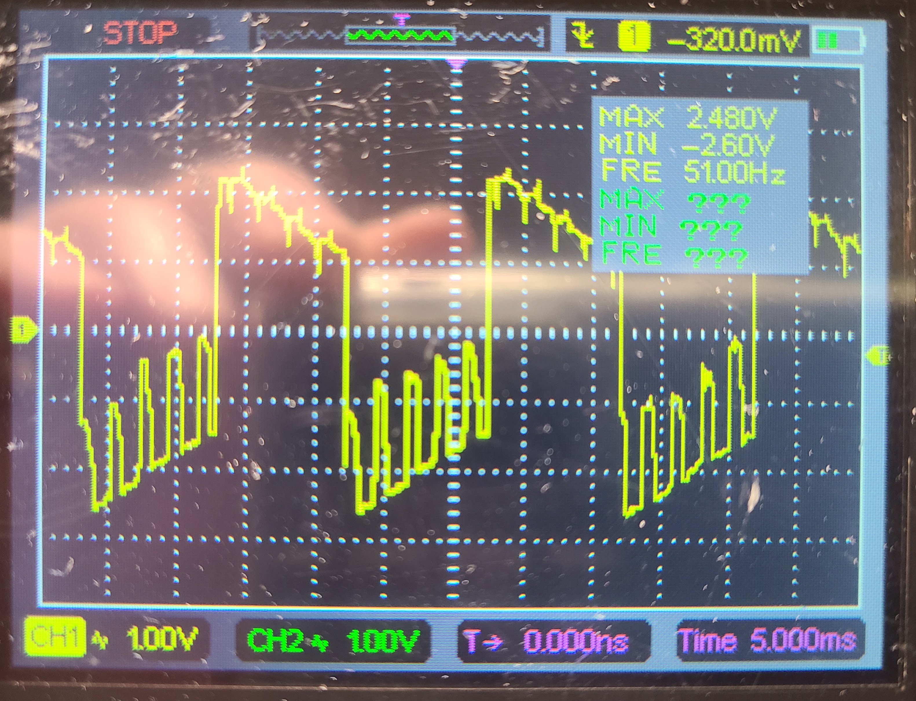
The scope trace of the tachometer above was taken at a PWM duty cycle of 40%. (Sorry for the lousy photo. My scope is not configured to let me take a real screenshot.)
The slight surprise was that the pulse outputs were not the nice, tidy square wave I was assuming. Instead, they had non-trivial ramps for the tops and bottoms of the waveform, gravitating toward the midpoint. The waves themselves are roughly 50% up and 50% down. There are some return-to-midpoint mini-pulses within each real pulse.
Hypothesis: The ESP32 might be counting unreliably due to the ramps on the top of the waveform.
The big surprise was in the voltage range of the tachometer pulses. To be honest, I didn't even give this any thought when I wired things up. On the scope, I could see that the pulse waveform was centered around 0 with the waveform going between roughly +/-2.5v. Just through dumb luck, the pulses at +2.5v were visible to the ESP32 3.3v input pins. The ESP32 spec guarantees detecting a HIGH on an input at 0.75*Vdd or higher, or 2.475v. That was pretty lucky, except for one thing. I noticed that as the PWM duty cycle went up, the waveform shifted down. I assume that's somehow related to the power draw for driving the fan. In some observations, I saw it go as low as about 1.8v at higher RPMs. (I'm a software guy, so how a +12v power input can trick a fan into producing output pulses that dip to -2.5v is puzzling to me right now.)
This is more than a hypothesis: When the PWM duty cycle gets high enough, the waveform drops low enough that the ESP32 does not see as many HIGH pulses, so the pulse count actually drops. This is not the fault of the ESP32, of course.
Surprisingly, the Intel spec cited above does not actually say what the voltage range of the tachometer should be, though it does say the signal should be pulled up to the 12v supply. I have already been using the ESP32 internal pull-up to 3.3v. The pullup makes some kind of difference, but I don't yet grok what it does. Various "someone on the Internet" postings make conflicting claims. Some say the waveform varies from 0v-12v, some 0v-5v, and almost all give the useless disclaimer to check the datasheet for the fan in question because it varies by manufacturer. The disclaimer is useless because you are unlikely to find a datasheet with that info for any US$10 case fan. (If you do, let me know. I'd like to read it.)
I'm still pondering how to resolve these two things. Luckily, observing the tachometer output is more of a curiosity of mine than a functional necessity for this project. I have plenty of time to figure it out. I know from real, physical experiments that all 3 brands of fans that I have on hand put out a pulse waveform that is generally in the area of +/-2.5v, and I know that logic inputs on the ESP32 are expecting 0v-3.3v, more or less. Sooner or later, I'll settle on a reliable way of doing that level shifting. My intuition is that some "too cheap to meter" transistors will do the job.
-
Musings on power options
09/05/2022 at 18:41 • 0 commentsI've been thinking about how to power things. Most PC case fans will run at lots of different voltages, but they expect to run at 12v (DC of course). If a different voltage is supplied, they just run at a different speed. There are some fans available that expect 5v, but they are for some reason a lot more expensive (maybe just market forces). For predictability and management, it's best if the power supply is steady, but it probably does not need to be regulated for running the fans as long as it's not grossly variable.
All along, I've been expecting to power things with a 12v DC wall wart or bump-in-the-cord power brick. I already have several spares from dead electronic components. (I've been following Tony Brobston's smart vent project. He ran low voltage power wires through his home's duct work from a central transformer. It's a tidy solution, but it may be a bit too involved and invasive for me.)
The ESP32 has a couple of power options.
- I'm planning to use dev boards that have the usual USB 5v input, but I don't want to run a second power cord to the register.
- You can feed 3.3v directly to a pin, but only if it's regulated. I'm trying to see if I can avoid the use of a regulator in the circuit, because....
- The ESP32 dev board has an on-board 3.3v regulator, and you can feed unregulated 5v-12v into a pin. For efficiency of the regulator, closer to 5v is better than higher.
I think I will be able to feed my 12v power supply into the overall circuit. That 12v supply will go directly to the fan power input (well, as I mentioned earlier, it will probably actually go to a MOSFET that can switch the fans completely off). Then a couple of voltage divider resistors will tap the 12v supply to provide something above 5v to the unregulated ESP32 input. For that last part, I'll have to check the stability of my supply voltage under load to be sure it doesn't drop too much and let the ESP32 input fall below 5v. That would also be undesirable for the fans, but that's less critical.
-
Arctic, et al, noise and speed test
09/05/2022 at 18:14 • 0 commentsArctic replied to my support question and stated that they give the noise figure at maximum RPMs for all of their fans. I don't know if there are different standards for measuring noise levels for fans. If they all use the same techniques, that makes Arctic's number pretty impressive. I'm going to start with those since I was able to get a 5-pack direct from their web site (but fulfilled by Amazon) for US$30. I have also recently obtained a couple other 92mm PWM fans for comparison.
Noise ratings for things like case fans are given in "dBA", where the "A" indicates "acoustic profile". It's a weighted measurement intended to reflect how the human ear and brain perceive the sounds. (Back when Bell Labs was working out stuff for the phone system, they referred to this as "psychoacoustics".) The other common measurement, not interesting here, is "dBC", which is typically used for louder sorts of sounds where hearing damage is more the concern than perception. This article from Honeywell does a good job of explaining the difference.
I don't have anything like a proper acoustic measurement environment or equipment. Since I am interested in ballpark and relative differences, I did the cheap and easy thing.
- I have a piece of gear that can generate the 25kHz pulse train with PWM duty cycles configurable in 1% increments.
- I powered the fans directly from a +12v bench power supply.
- I bought the least expensive audio level meter I could find. (The seller sent me a lower-featured model, so it wasn't really a bargain.)
- I marked a position on the workplace and put each fan in exactly the same place when it was being tested.
- I set the audio level meter in "no timeout" mode, put it about a foot away from the fan position, and did not touch it at all for the duration of all the testing.
I was surprised to see that the background noise level in my basement "acoustics lab" was 44.4 dBA. I rechecked that several times during the testing, and it was pretty consistent. On the other hand, I could see the audio level meter jump around whenever anybody was walking around upstairs. And, if someone flushed a toilet, that put a temporary pause in the testing effort. The audio level meter was always jumping around at least a bit, so my measurement technique was to adjust the PWM duty cycle, wait a bit for the fan to change speed, and then "eyeball" what I felt was the average reading on the meter. Probably any difference of 0.2 dBA or so is not meaningful.
Other than the Arctic, I only had one of each fan. For the Arctic, they include cabling for chaining them together. I tested those with 1, 2, and 3 active Arctic fans since 3 fans is the target configuration for the project.
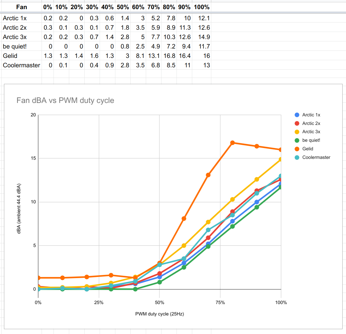
Here are the results, numerically (with 44.4 subtracted out) and graphically. You can find the exact models of the fans in an earlier project log.
![]()
I also measured each fan with no PWM control input at all (ie, that wire was disconnected). Each matched the 100% PWM duty cycle number, which is what the spec calls for.
Most of the fans did not show any noise difference until somewhere between the 30-40% PWM duty cycle. (See below for RPM measurements.) The exception is the Artic fans, which started changing between 20-30% PWM duty cycle, which matches the manufacturer's specs. Once the fans started reacting to the PWM changes, the correlation was roughly linear, except the Gelid, which rose rapidly and then plateaued. At the higher end, all of the fans were loud enough that they would be noticeable in a quiet bedroom. The non-annoying usable range is probably somewhere like 20-30% up to 60-70% PWM duty cycle. With 3 fans wired separately, there is the possibility of tuning them at different PWM duty cycles if that proves useful.
The noise winner was the be quiet! fan, with the Arctic a close second. The Coolermaster was not too far off, but it was similar to two Arctic fans. The Gelid was the loudest of all fans tested at all PWM duty cycles.
After I resolved a measuring problem, I ran another set of tests to measure fan speeds at various PWM duty cycles. For these tests, the PWM was generated by an ESP32, again in 10% increments. In an intervening experiment, I was able to see that those signals were very accurate. I measured the tachometer output of each fan with an oscilloscope that had a direct frequency read-out in Hz. The graph below scales the 2 pulses per cycle to RPMs.
![]()
It was pleasing to see that all of the fans were reasonably close to the spec values for minimum and maximum RPMs, and they had fairly good linearity in the expected part of the graph. The exception, again, was the Gelid, which reached maximum speed at 80% PWM duty cycle and was flat above that. The Arctic starts reacting at between 10% and 20%. The manufacturer says it's "absolute standstill 0 dB" below 40%. That clearly is not true, since the fan is turning slowly even at 0%, but it is pretty quiet down in that area.
-
Temperature drops
08/23/2022 at 00:58 • 0 commentsOne common scheme for controlling a register booster fan is to detect a temperature difference in the ductwork. If the temperature drops while in "AC mode", the HVAC is blowing cold air. If the temperature goes up while in "heating mode", the HVAC is blowing warm air.
I wanted to see how simple this idea would be to implement. I put a temperature sensor inside the ductwork in one of my upstairs rooms. I also have a smart thermostat from which I can find out exactly when the AC or heat is on. (It's a warm summer here, so it's AC.) Both of those devices are integrated into my Home Assistant server. Here are graphs of a few days or so of both.
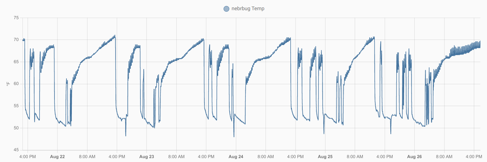
First, the temperature inside the ductwork:
![]()
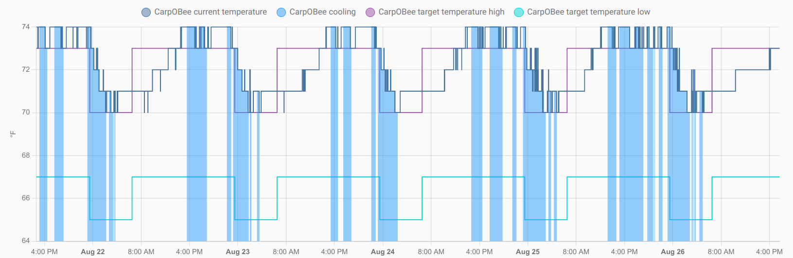
Next, the smart thermostat activity.
![]()
The solid blue areas are the times when the AC is active. It lines up nicely with the temperature drop of 15-20 degrees (F) in the ductwork. The smart thermostat also has a control to let me run the fan some configured percentage of the time for circulation and filtering purposes, but that is not reflected in the graph.
-
Control freaking
08/20/2022 at 19:19 • 0 commentsWithout even knowing if this entire idea will do what I want, I've spent some mental energy thinking about the user experience of controlling it. (That's not the right way to go about things for project management, but that's not the way some brains work. :-) ) If I use an ESP32 to control the fans, that gives me a lot of flexibility in the control stuff.
It goes (almost) without saying that the units will report their sensor and operational state data to my home automation setup. I use Home Assistant and will probably use MQTT to tie into that. It would be entirely possible to control the units from Home Assistant. I will probably do that, but I don't want that to be the only means of controlling them, for the following reasons:
- Most of the rest of the household is not so interested in interacting with nerdy Home Assistant. I'm trying to cure that by making a ultra user-friendly wall panel system, but that's a longer-term project.
- If we have house guests, I want them to be able to have some control over the guest room climate without needing to take a community college course to understand how to do it. I don't even want to force them to have an app or even a computer. I want to give them some kind of in-room control. (A wall panel tied to Home Assistant could do that, but see previous bullet.)
- If I were to someday sell this house, a lot of my home automation infrastructure would go away, including my wifi and my Home Assistant server. Could I leave the register booster units in place with controls feasible for the new owners to use without requiring a lot of fiddling around?
I've been thinking mostly about some kind of local control UI for the ESP32 in the register. Let's call that R-ESP32. My registers are on the floor, so I don't really want to have some piece of electronics sticking out above the register grating all the time. I thought about some kind of "display with knobs and buttons" gadget that could plug into some wire or socket that barely protrudes from the register grate. To the average non-techy person, even plugging a provided box into that sort of thing in someone else's house might seem overly invasive.
Can I do something wireless with a separate box or wall panel? There is some chance I can run the fan and controller DC power wires through the ducts rather than using a wall wart. If that turns out to be possible, then there would be nothing sticking through the register and the vent opening, and that makes a wireless control gadget very desirable. There are plenty of off-the-shelf components that integrate an ESP32 and some kind of display. Even without that, integrating those two things is pretty painless. Add a few knobs or buttons, mount it in a convenient wall location in a nice enclosure, and you're sitting pretty. Let's call that gadget he UI-ESP32.
With an ESP32 on both ends, there are obvious possibilities for having them talk to each other (even after subtracting out various wired options). I expect the R-ESP32 will already be talking to Home Assistant over wifi. Using the same or a similar pathway for linking the two ESP32s would be straightforward. The cost of that would be involving the wifi router, and maybe even the Home Assistant server, in the pathway. That's not a deal-breaker, but I'd rather avoid it if I can. Bluetooth Classic or BLE are possible and would give that local point-to-point interaction. (I'm not sure about complications of using both wifi and BT on the same ESP32. I know it can be done, but I'm not sure if there is any trickiness involved since they use the same radio.)
I think I will use ESP-NOW. ESP-NOW is an Espressif-defined protocol for communicating with short packets over IEEE 802.11 physical links. That is, it uses the same radios and channels as wifi, but most of the information within the packets is "custom" for the ESP-NOW protocol. I think (but I'm not yet sure) that it will be simple to use both traditional wifi and ESP-NOW side by side without too much complexity or hassle.
The overall flow of things is something like this:
- Most of the time, the R-ESP32 is autonomously controlling the fans according to it's configured settings.
- The R-ESP32 is also periodically sending its sensor and operational data to Home Assistant (probably by publishing to an MQTT topic to which Home Assistant is a subscriber, but that doesn't matter here).
- In some yet-to-be-defined way, Home Assistant can be used to modify the configured parameters for the R-ESP32.
- Most of the time, the UI-ESP32 gadget is not connected to any R-ESP32. Maybe it's even powered off completely. When it's turned on or a "connect" button is pressed or whatever, it initiates communications with an R-ESP32.
- The UI-ESP32 can ask for all of the sensor, operational, and configuration data from the R-ESP32. It can provide ways for configuration updates sent back to the R-ESP32. There's some way to resolve conflicting updates from multiple sources, though I suspect it will resolve to "last writer wins" and that will be good enough.
There's an interesting user experience puzzle in there, or in the system more generally. The R-ESP32 is controlling the fans according to its configuration for vent opening temperature sensor reading, fan speeds, etc. But that is quite a bit different from the notion of a person saying "it's just a bit too warm in this room; fix that". That's a problem for another day.
Ventbot: warm side cool, cool side warm
A DIY register booster project to even out the temps around my home.