 J Gleyzes
I have been testing for several weeks a new circuit to create a better AC current with a current sensor to adapt the frequency.
Schematic:
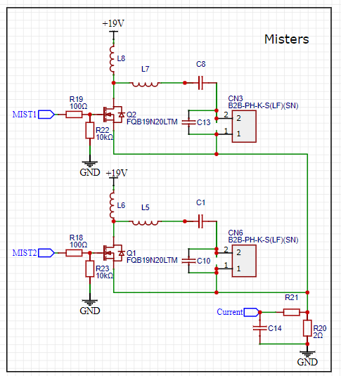
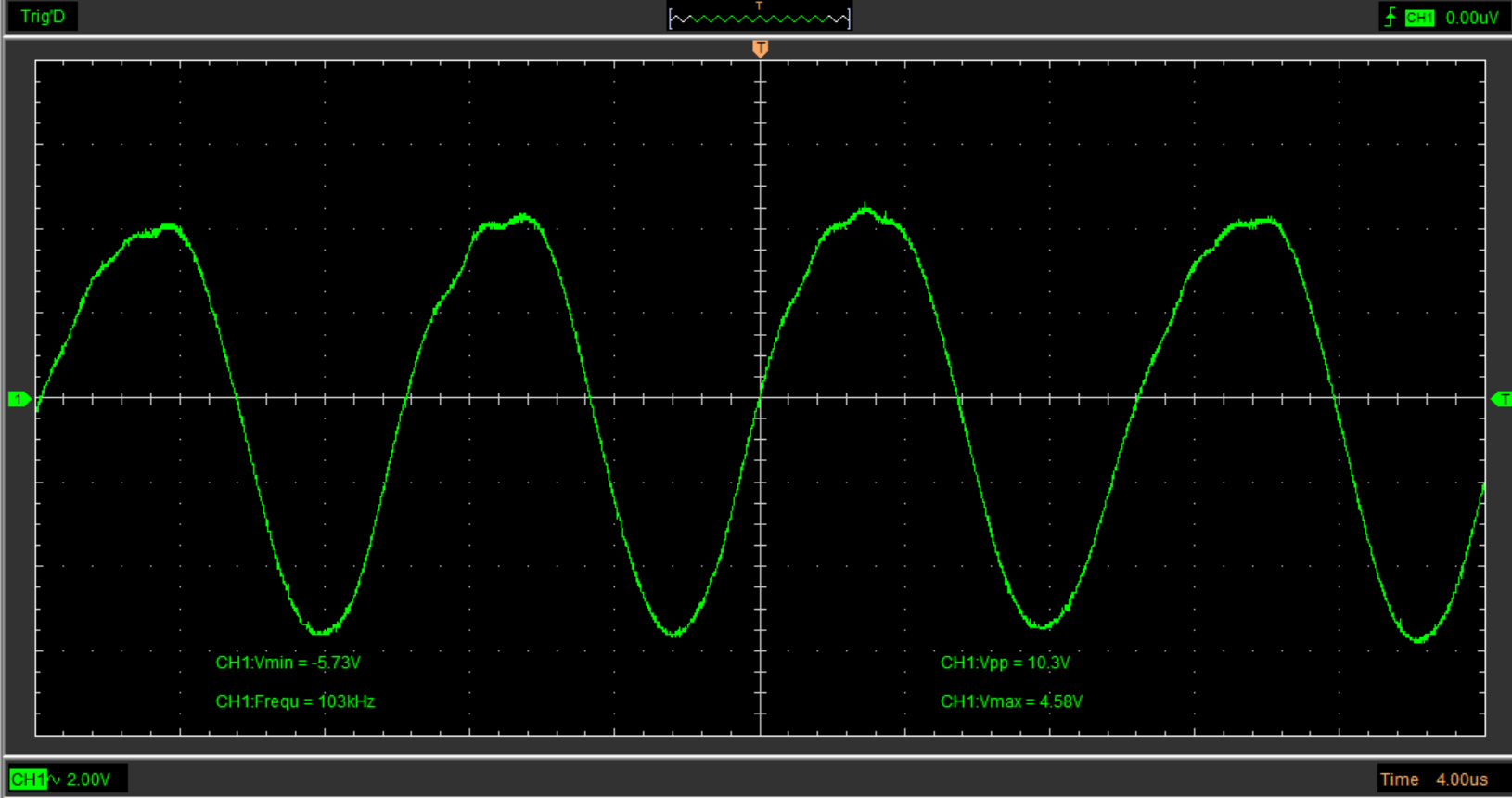
By adding coil L7 and capacitor C13, the generation of alternating current is balanced in the negative and positive directions.
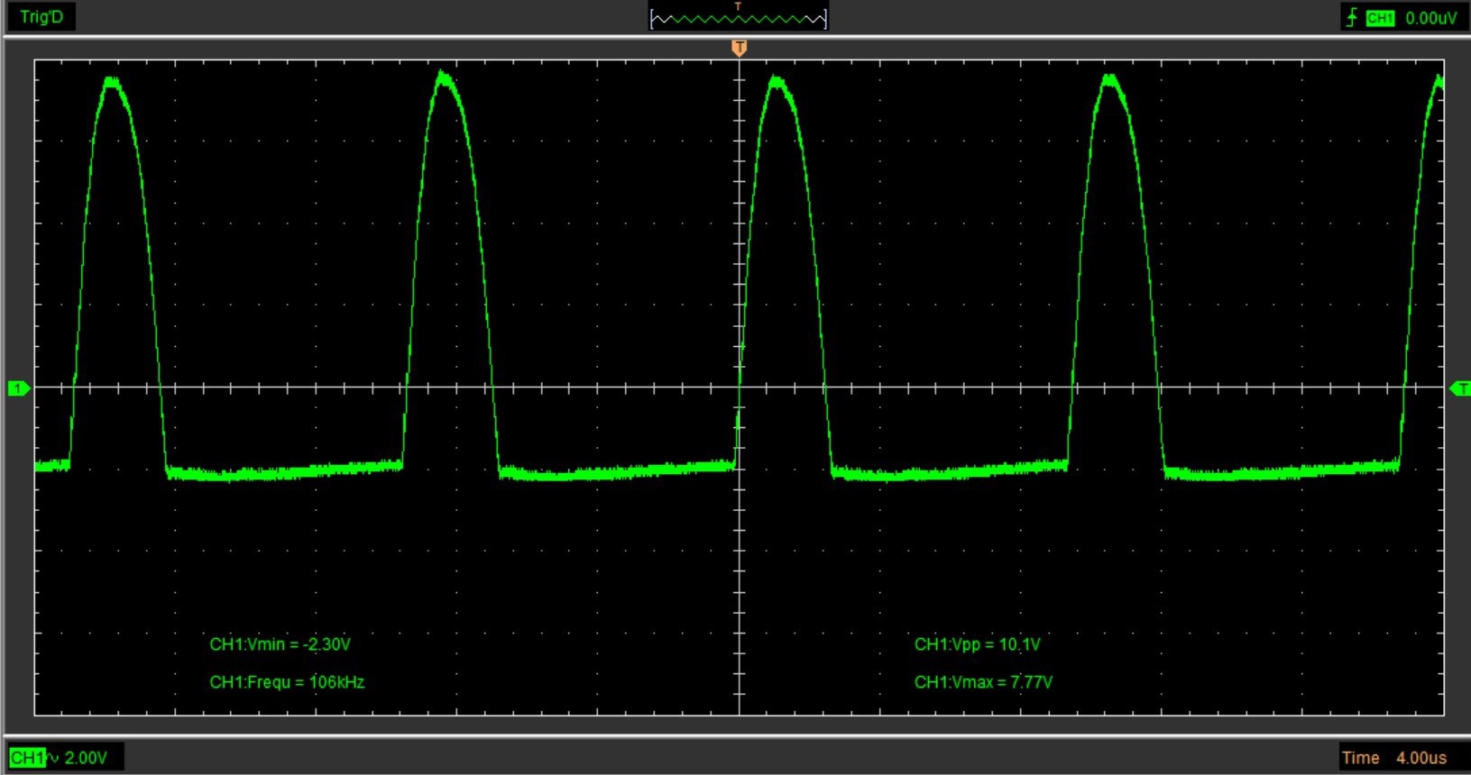
Old circuit:
New circuit:
I also added a shunt resistor to measure the current. By changing the frequency we can detect the peak of fog creation which corresponds to the current peak.
And for example for a disk sold with a resonance frequency of 108kHz the peak of fog creation is at 100kHz.
I have ordered the new PCB with the modifications. I will test it before publishing it.
Discussions
Become a Hackaday.io Member
Create an account to leave a comment. Already have an account? Log In.