 Drew Pilcher
Right now I'm working on building an "automatic transfer switch". This device will switch the load from my solar system to mains if the inverter shuts down.
I'll document that in another post, but one problem I had to solve to make it work was to detect the line voltage with an arduino.
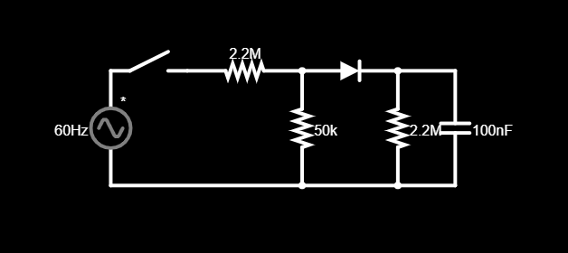
At first it sounds pretty simple right? Reduce the voltage with a resistor divider, then rectify it with a diode and a cap.
But the issue with this is I have 2 inputs, and for electrical safety I want to switch the hot AND neutral. That means I need some kind of isolation if I want my arduino to be able to monitor both.
Here's the solution I came up with using parts I had lying around:

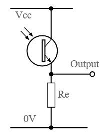
It's an opto-coupler utilizing a phototransistor and a neon lamp instead of a LED. Although the lamp is fairly dim, it produces a good response from the photo-transistor. I used this arrangement with a 680k resistor and a 5V power supply:
I don't know the photo-transistor part number because it was just something from my junk box, but the lamps were still in the bag; the part number for those is GT-NE6S1325T
I'm not going to lie, I forgot neon lamps need current limiting resistors (150k for this one), and the lamp exploded instantly the first time I tried it. Luckily, I did have the foresight to put on safety glasses before flicking the switch on a circuit connected to mains. :)
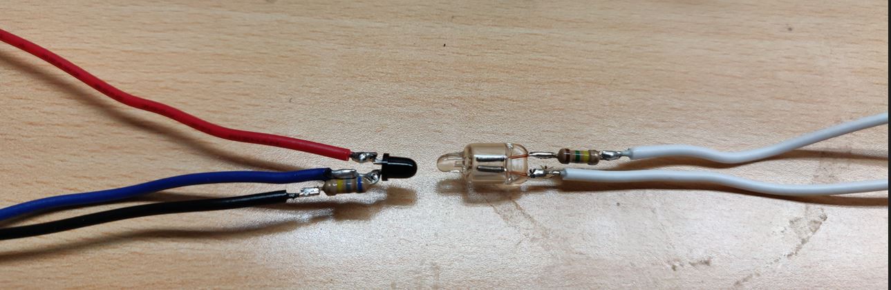
With the circuit tested, I assembled it like this:
Then I added the following layers;
- Heatshrink on the individual wires, especially the mains ones (not pictured)
- Clear heatshrink over the whole assembly (not pictured)
- A layer of aluminum foil over that. Both to block ambient light, and reflect light internally:
![]() Then a layer of heatshrink with internal adhesive (to add some rigidity):
Then a layer of heatshrink with internal adhesive (to add some rigidity):
 Then a layer of heatshrink with internal adhesive (to add some rigidity):
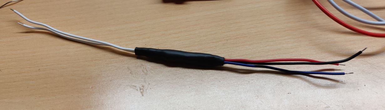
I tested the module again after assembly and it works perfectly! I might need some filtering of the output signal if it has a 60Hz flicker, but my multimeter reads it just fine.
Discussions
Become a Hackaday.io Member
Create an account to leave a comment. Already have an account? Log In.