 kaimac
I made a couple of changes:
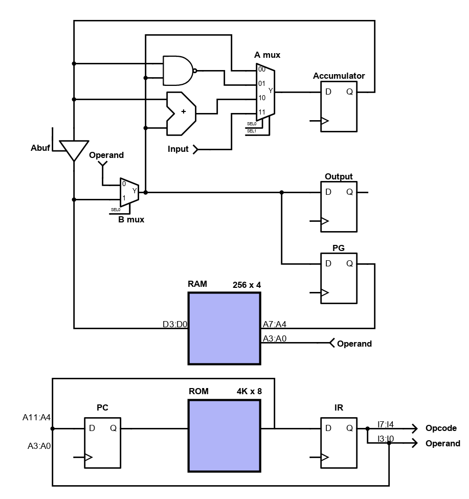
- The page register PG is set via the B mux, so it can be set to a literal or to the accumulator value via ABuf.
- Same with the output register
spg 3     ; set page register to 3
pga       ; move accumulator value to page register
out 5     ; set output register to 5
out       ; move accumulator value to output register
These changes will add some functionality while simplifying the instruction decoding - always nice when that happens!
To make this diagram I tried using Digikey's online schematic tool. The end result isn't too bad but it's not particularly nice to use. If anyone has any good suggestions for tools for making this kind of block diagram, please let me know!
Discussions
Become a Hackaday.io Member
Create an account to leave a comment. Already have an account? Log In.
Hi @Kyle McInnes, I like inkscape (https://inkscape.org/). It's good for making block diagrams, but it takes a little learning to get started!
Inkscape extension to assist creating logic circuits symbols:
https://github.com/fsmMLK/inkscapeLogicGates
Are you sure? yes | no