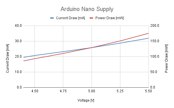
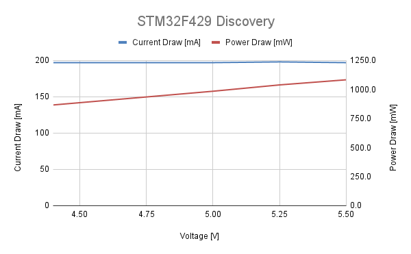
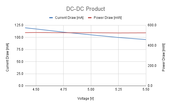
According to the USB 2.0 standard, the USB Vbus voltage can range from 4.4V to 5.5V. A USB Device needs to be able to work in at least that range and probably lower due to the voltage drop in the cables. With the USB Power Injector, that test is trivial.
For this test I have selected three devices:
- The Arduino Nano. On it the VBus is connected directly to the Atmega328.

- STM32F429 Discovery Development Kit. On it VBus goes trough a 3.3V low drop linear regulator before going to the STM microcontroller.

- A USB powered single board computer I developed for work. Unfortunately, I can't go in to details on it, but it uses DC-DC convertors that drive the main processor.
The Arduino and the single board computer will be idling in an infinite loop. The STM Discovery will be running the default demo application.
All three board will be tested at different voltages in order to determine if they are function correctly. While I’m at it, I’m going to measure the current consumption of each device at each voltage in order to compare each power supply scheme characteristics.


All three devices worked in the voltage range from 4.4 to 5.5V. As is usual for boards powered by linear regulators, the supply current for the STM discovery stays more or less constant, regardless of the voltage. Likewise, the DC-DC convertor powered single board computer keeps the power draw constant, regardless of the supply voltage. Since the Atmega328a was not powered by a constant voltage, its current and power draw had a clear rising trend, if we increased the voltage. Knowing the behaviour of common power supply schemes can help us track problems in products we are developing, if we are not observing them due to a failure in a component or an error in the design.
 Nikola Manolov
Discussions
Become a Hackaday.io Member
Create an account to leave a comment. Already have an account? Log In.