 sdfgeoff
Rather than have to screw and unscrew something to get access to the internals, it would be cool to have a twist-lock mechanism: twist a handle by 45 degrees and the internals slides out on it's rack.
My first attempt at this involved printing out the whole lid mechanism. This would give me a size and visual appearance estimate:
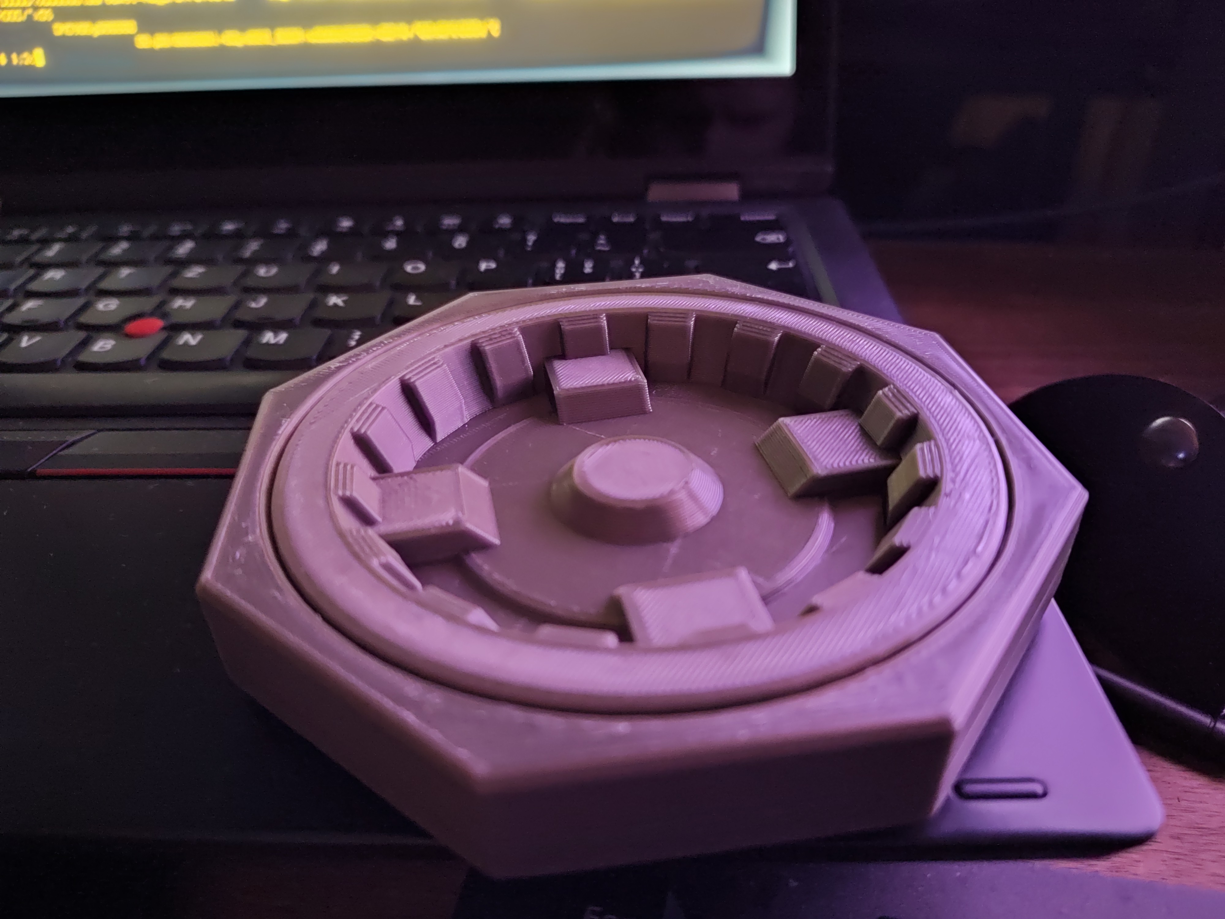
3 hours later I had a physical part. There are two parts here: the circular "handle" which can rotate relative to the octagonal "lid". The "lid" has some print-in-place sliding bolts that allow it to engage with another par. Unfortunately the tolerances were off, so it was non-functional (print in place parts were stuck together). Still, it allowed me to fiddle with something in my hands, and spurred a bunch of thinking about how the latch would work. So a bunch of latch test prints followed:
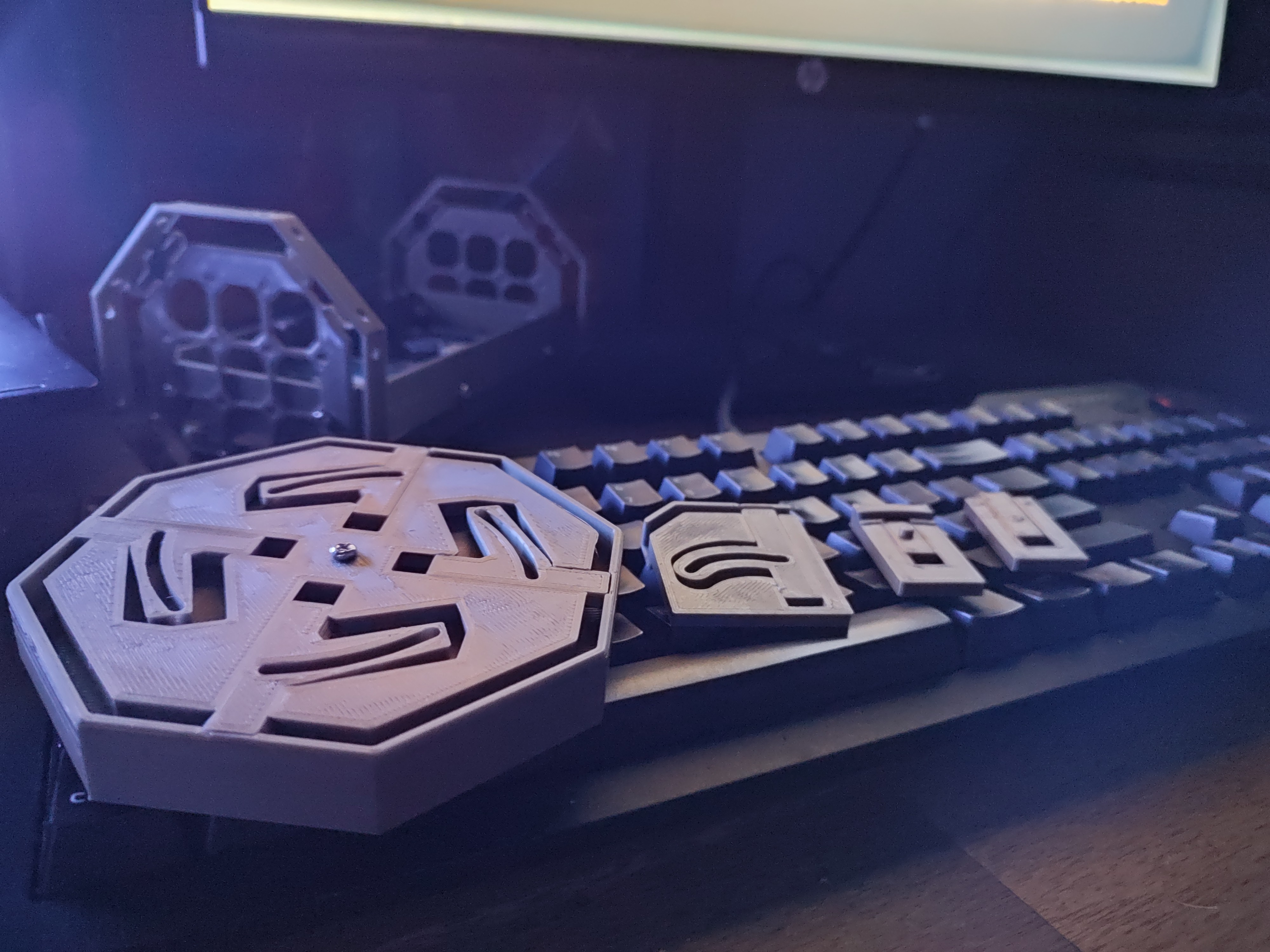
These tried different tolerances and slide designs.
From left to right:
- Print 1. Initial print (incorrect tolerances). Additional bolts will go through the slots so that as the two parts are rotated relative to each other the pins are driven in/out.
- Print 4. Final latch design, similar to the initial but the slider is shaped like >=< rather than <=> which gives better stiffness with less steep overhangs. It also has a flipped drive direction - the pin is extended when the bolt is in line with the pin. This means that any load on the pin is well supported by the mechanism.
- Print 3. Printing an engage pin - the idea is that the slot would be on the circular handle part. This design reduces the part count, but results in their being exactly one bolt holding the handle on. As this is meant to be a rugged design I decided to go back to the slot and bolt design.
- Print 2. Tolerance test print.
Then came printing a new suspension plate for it to mate with:
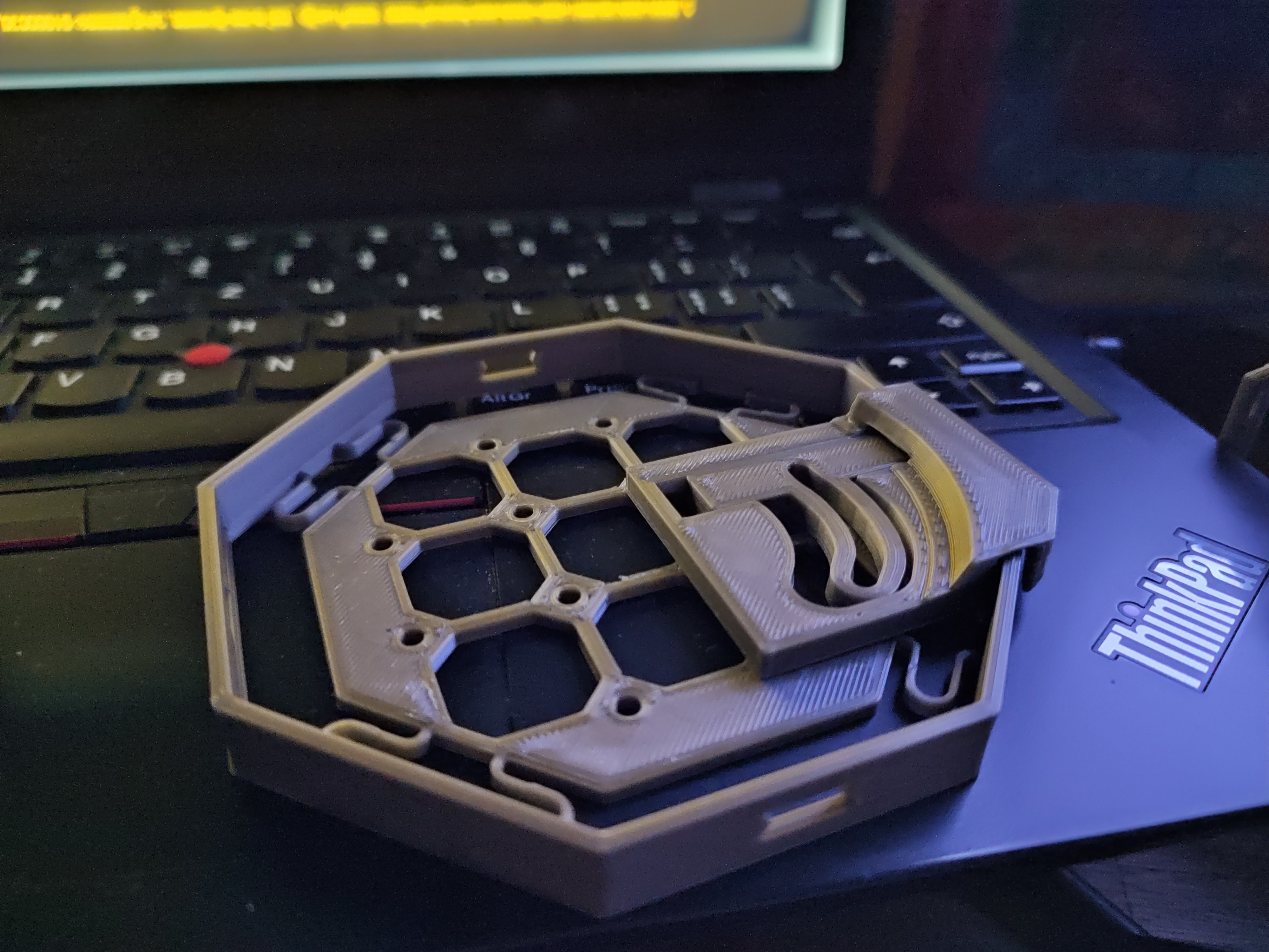
Immediately after putting the two parts together I slapped my forehead. Duh! I'd forgotten to leave any space for the suspension plate to move, and there wasn't even room for the bolt heads!
Well, that'll be tomorrows job. My printer is too loud to run at night.
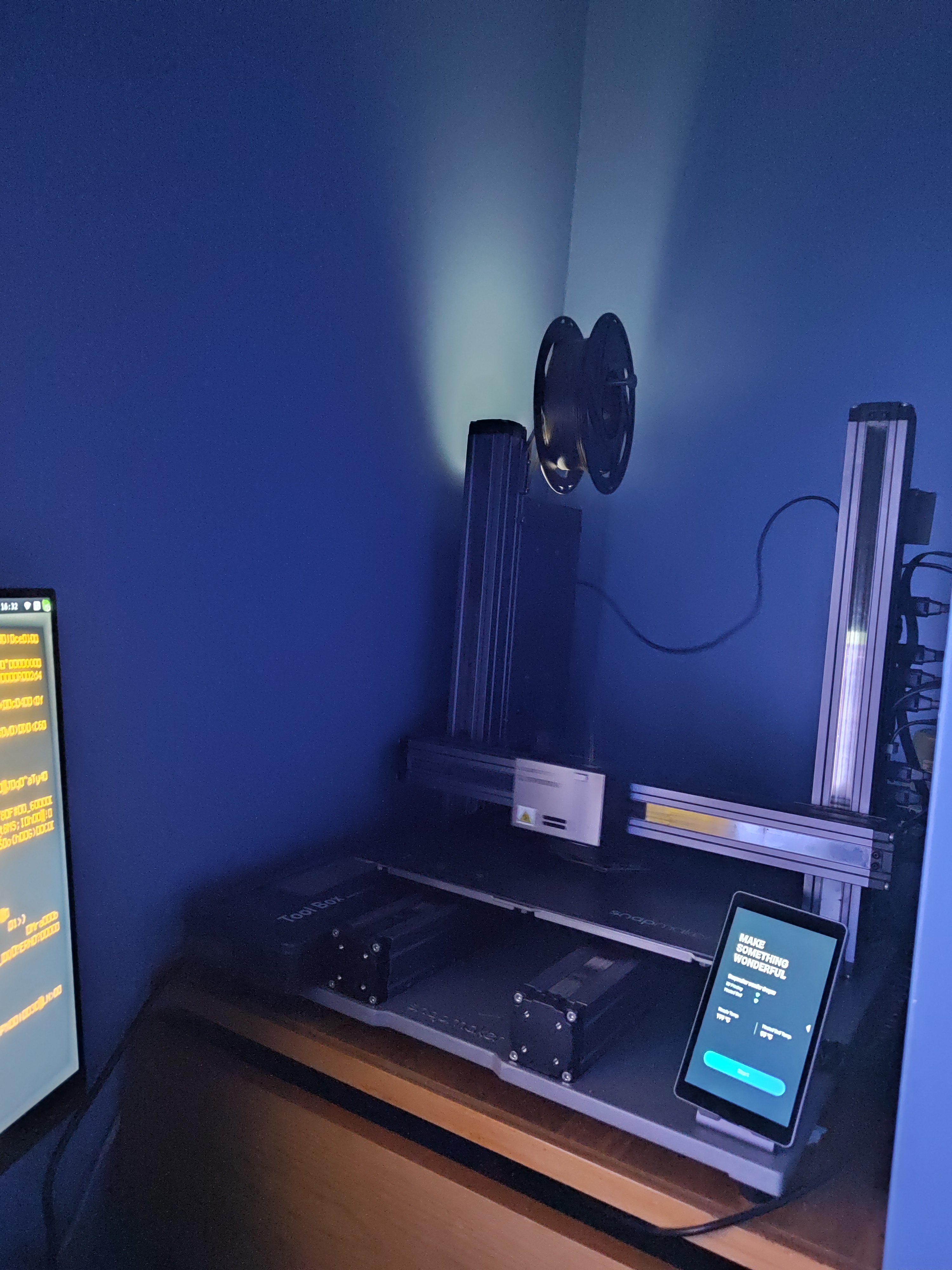
For maximum cyberpunk feels I'm taking these photos at night illuminated solely by my computer monitors. So while they sure aren't top quality images, I'm just going to say it: modern phone camera's are pretty amazing!
Discussions
Become a Hackaday.io Member
Create an account to leave a comment. Already have an account? Log In.