Close
0%
0%

DIY Landslide Warning System

Japan is a mountainous country and many landslides occur during the rainy season. This device detects and reports signs of landslides.

Similar projects worth following
Most of Japan's land area is mountainous and characterized by extremely heavy precipitation. Because of this geographical factor, every year during the typhoon season, large-scale disasters occur throughout the country.

One of the disasters that can cause major damage is a landslide. Before a landslide occurs, slight changes occur in the topography, and these changes can be observed as various precursor phenomena. If these precursor phenomena can be detected in advance and lead to evacuation, it may be possible to reduce human suffering.

Therefore, in this project, we have developed a device that detects landslide precursor phenomena and issues an alarm.
Widespread use of inexpensive and easy-to-use warning devices would be a simple and effective way to prevent the spread of damage.

FEATURE

This device is intended to be a DIY alarm system that can be built using Spresense and as many readily available components as possible. We envision this device to be used by people living in mountainous areas or on slopes in the foothills of the mountains, where it can be easily installed behind their homes or on their property.
The basic principle of operation of this device is to sense changes in the inclination of an erected pile.

Our research into existing technology shows that similar concepts already exist. However, since it is necessary to operate a large number of devices to detect predictive phenomena that can occur anywhere, a key issue is to further reduce the cost of the devices.
The main focus of this project was not to develop a multifunctional device, but to develop a device that is easy to operate and can be implemented as easily as possible by people with no knowledge of electronics or electricity.
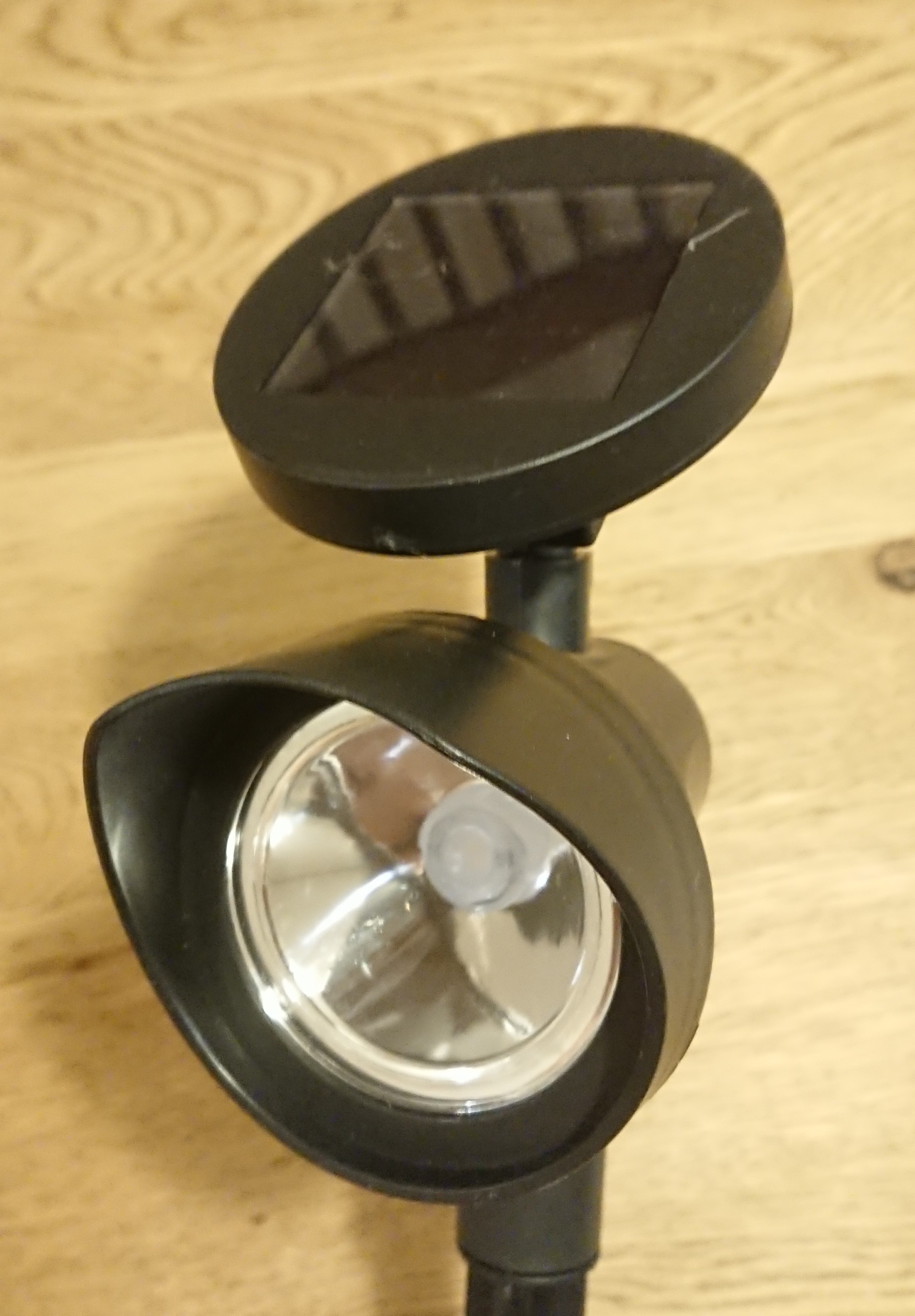
The main functions of the device can be implemented by using common garden lights or by combining components that can be purchased in stores.

Main Functions and Features

  • Easy installation by simply sticking the device into a garden-light enclosure
  • Detects changes in the tilt of the device using an acceleration sensor
  • Alert indication by flash using LEDs of the garden light
  • Transmission of alert signals via Wi-SUN communication
  • Alert information is sent from the receiving device to an arbitrary terminal via MQTT
  • Alert display device receives the alert information and displays the alert.
  • Supplemental power supply by solar panel of the garden light
  • Transmission and recording of data to google cloud(spread sheets).
  • Management of data by google apps scrept
  • Infomation management of each terminal and display of map information by smartphone apps(glide)

In operation

Field test.

Field test #2

Smartphon Apps

Installation

When installing the device, simply plug the device into the location you wish to monitor, stand it up, and turn on the power. (0:04~)
When the power is turned on, the acceleration sensor measures the tilt of the device and memorizes the initial state, and the startup completion status is transmitted via Wi-SUN communication.
The LED for alarm indication flashes once when the system starts up, and flashes twice after successful Wi-SUN communication to confirm normal startup. (0:14~)
When startup is completed, the system enters Deepsleep.

When no abnormality is detected

By default, Deepsleep is released every hour to measure the tilt. In the above movie, Deepsleep is set to 3 seconds for operation check. If the difference from the initial tilt is less than the threshold value (5° by default), the system sends a "no abnormality" status and the value of the angle change, and enters Deepsleep again.

When an abnormality is detected

If the difference between the inclination of the device after the release of Deepsleep and the initial inclination is greater than the threshold value, the LED of the garden light flashes and an alert status is sent via Wi-SUN communication.

Receiver-side device (Raspberry Pi 4B)

A Raspberry Pi 4B is used as the receiving device, and a Wi-SUN USB dongle BP35C2 is used to receive Wi-SUN communications.
It also serves as an MQTT server and sends alarm data to the alarm display device or any device.

Alarm display device (M5Stack)

When alarm data is received from the receiving device, it displays the ID of the sensor terminal that detected the abnormality, and indicates the alarm with text, background color, and alarm sound. (0:45~)

System Configuration

The overall system configuration is as follows

Spresense is used as the controller for the sensor section to calculate the device's tilt from the BMI160's accelerometer values. The measurement results are sent to the receiving device via Wi-SUN communication.
The receiving device, a Raspberry Pi, uses python for Wi-SUN communication and data processing, and Node-RED for running the MQTT server and...

Read more »

LED_SWITCHING_BOARD.png

LED Switching Board Schematics

Portable Network Graphics (PNG) - 11.51 kB - 08/26/2022 at 05:27

Preview

LandSlideAlertSystem002.m5f

M5Stack UIFlow alert display

m5f - 10.56 kB - 08/26/2022 at 05:15

Download

wisun_rcv5.py

Raspberry Pi Wi-SUN reciever

py - 2.89 kB - 08/26/2022 at 05:14

Download

wisun_init.py

Raspberry Pi Wi-SUN init

py - 628.00 bytes - 08/26/2022 at 05:14

Download

bp35c0-j11.cpp

Spresense Wi-SUN library

cpp - 14.08 kB - 08/26/2022 at 05:14

Download

View all 7 files

View all 16 components

  • 1
    Disassemble garden lights

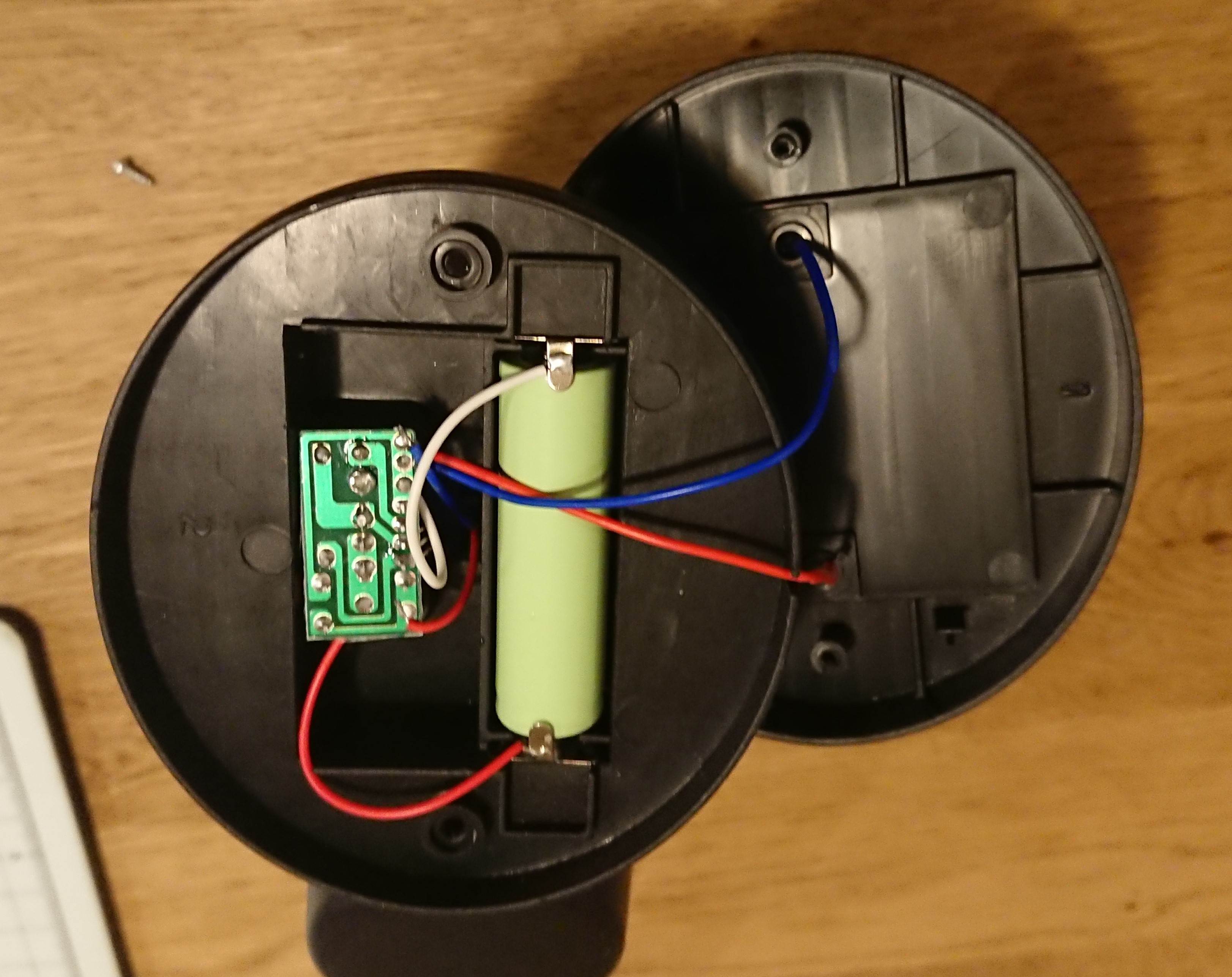
    Disassemble the solar panel section at the top of the garden light, which contains the battery and circuit board.

    Remove the two screws on the back of the solar panel and open the housing to access the circuit board and batteries for battery charge control and LED lighting control.


  • 2
    Replace the battery

    Ideally, the system should be operated using only the power generated by the solar panel, but since we do not have sufficient know-how in power saving, we will change to a rechargeable battery with a higher capacity.

    The capacity of the included battery is 200 mAh, but we will replace it with a 2400 mAh battery.

    Below is the standard battery and above is the battery used.

  • 3
    Replacing the cables on the charge control board

    The garden light uses an IC called YX8055 to charge the battery while the solar panel is generating power and to turn on the LEDs when the power generation stops.

    Disconnect the power supply cable to the LED and relocate it to the main power line. Power is constantly supplied to the SPRESENSE through this cable.

    The upper image is before the cable was replaced, and the lower image is after the cable was replaced.

View all 12 instructions

Enjoy this project?

Share

Discussions

Ted Nunn wrote 08/31/2022 at 12:32 point

Excellent. Thanks for elaborating!

  Are you sure? yes | no

Ted Nunn wrote 08/28/2022 at 23:16 point

I like what you've done here to re-purpose the garden light enclosure and use the built-in solar capability! I'm wondering how you came to choose the Spresense board for this vs. some other (possibly cheaper) controller. Are there specific capabilities of the Spresense that you needed that other controllers lack?

Also, I believe the Spresense has a built in IMU. What does the break out accelerometer provide that the onboard IMU doesn't for this application?

  Are you sure? yes | no

AIRPOCKET wrote 08/31/2022 at 01:21 point

Hi, thanks for your interest in my project.

Unfortunately, Spresense does not have an IMU so we used an add-on board.

To your question as to why I chose Spresense, I would say "because it's out there", but there are three reasons why I chose to use Spresense.

The first is that it can save power, but we have not yet obtained sufficient functionality for power saving and need to improve it.

The second is that it is compact. It must be small enough to be placed inside a garden light.

Third, it must be equipped with GNSS. Although not yet implemented, this device is intended for a large number of operations, and we believe it will enable more effective monitoring by measuring its own position with GNSS and confirming the position information with an application on the receiving end.

I am also envisioning a simplified version using ESP32 and a version with enhanced communication functions using LoRa, but I would like to determine which combination would be best based on the results of field tests.

  Are you sure? yes | no

Similar Projects

Does this project spark your interest?

Become a member to follow this project and never miss any updates