 Open Green Energy
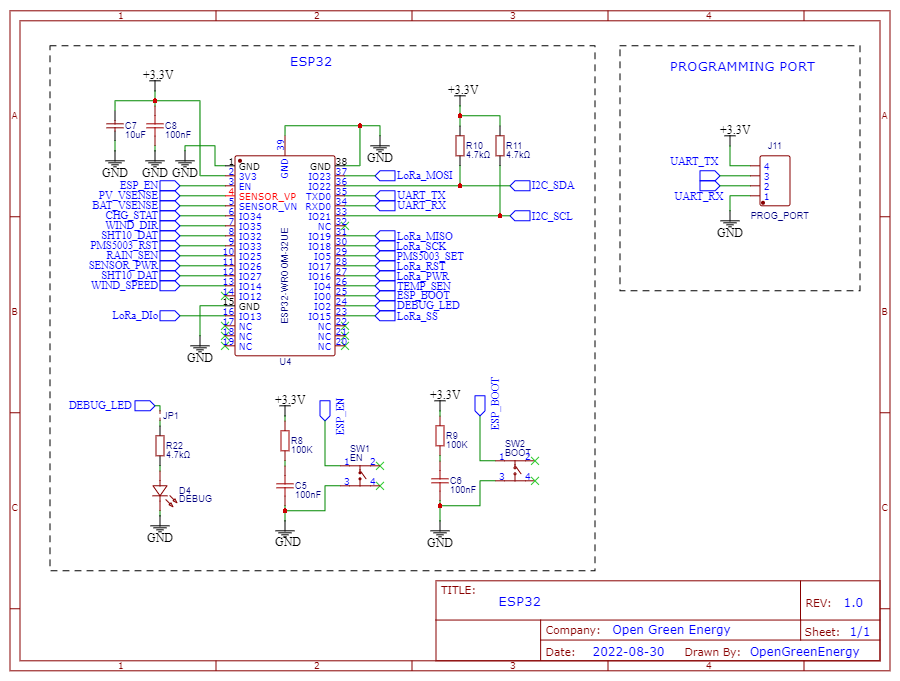
The main controller for this project is an ESP32-WROOM32 microcontroller. The 3.3V power supply from LDO is fed to the 3V3 pin of ESP32 with input filter capacitors C7 and C8. The two resistors R10 and R11 are pull-up resistors for the I2C bus. LED D4 with a current limiting resistor R22 is used for indicating the debugging status. A jumper JP1 is used to enable or disable the debug LED. If you need this LED, you have to short the jumper JP1.
The Program port J11 is used for connecting the board with a programmer to upload the firmware.
Discussions
Become a Hackaday.io Member
Create an account to leave a comment. Already have an account? Log In.