 Alvaro Barcellos
As reference pinout for ZIF socket, prefer AT27C040:
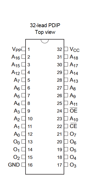
Considering the first 8 pins ( 1, 2, 3, 4, 37, 38, 39, 40) reserved for I2C and SPI, then changes are:
| ZIF | REF | A | B | NC |
|---|---|---|---|---|
| 5 | 1 | VPP | A18 | NC |
| 7 | 3 | A15 | A14 | VPP |
| 35 | 31 | A18 | WE | NC |
| 34 | 30 | A17 | VCC | NC |
| 33 | 29 | A14 | WE | NC |
| 32 | 28 | A13 | VCC | NC |
| 29 | 25 | A11 | WE | X |
| 28 | 24 | OE | VPP | X |
| 20 | 16 | GND | GND | GND |
PS. NC for not connected and X for must be, GND included for mark.
the schematics altered to comply.
dip switch 01 and 02 for eeproms:
to review:
AT28C16, (01 ON: S6, S8, S9), (02 ON: S3)
AT28C64, (01 ON: S2, S4, S7, S9), (02 ON: S3)
AT28C256, (01 ON: S2, S4, S7, S9), (02 ON: S4)**
SST39SF040, (01 ON: S1, S3, S5, S7, S9), (02 ON: S3)
M27C512, (01 ON: S2, S3, S5, S7, S10), (02 ON: S3)
W27E257 to review
AT24CXXX ALL OFF.
update:
for W27E257 pin 1 is VPP and pin 28 is VCC
Discussions
Become a Hackaday.io Member
Create an account to leave a comment. Already have an account? Log In.