 WalkerDev
In my last headset lens design, I had an issue with
- A lack of overlay
- The walls of the enclosure being able to be seen within the lens
- The design not being very reusable
For this new design, I focused on creating a compact, reusable lens that could work across multiple projects. At the same time, I realized I had completely forgotten how to design lenses in general. This is VERY, very bad for me (mostly due to the fact that 2024 was an incredibly slow year).
So, I’m going to walk through how I created this new lens!
To start, I kept three things in mind: my lens size, the amount of overlap I wanted, and the headset’s dimensions.
I’m using a 70mm lens, and I want the inner box to be around 140mm × 55mm at most. I also wanted to match the Quest 2’s lens overlap, so I calculated that the ideal radius should be about 27.5mm. This worked well with my display, which is 50 × 58mm. I created a box for it with 3mm-thick walls on each side and added a placeholder 1mm layer for the lens to sit on. In CAD, I’ll adjust this to the correct thickness for the actual lens. To further improve the design, I replaced the lens shape with a square rather than following the previous pattern, which helped resolve a prior issue.
Next, I took a 70mm circle (representing the max lens size) and a 55mm lens (representing the desired overlap) before splitting them in half. I chose 55mm because I need a minimum lens size of 58mm, ensuring enough space for a central support piece later.
To estimate the bridge size, I aligned the centers of both circles exactly 58mm apart (the minimum IPD I want).
At this point, the bridge is extremely thin (only 2mm at its narrowest) but I have a trick in mind to make this work.
With that sorted, I added a random distance between the lens box and the polarizer (which is now a simple rectangle rather than the complex shape it had before).
Now, onto the lens itself. I took the circle, cut it down to 55mm (between top and bottom), and made a hold for it. In CAD, I’ll tweak the height by about 0.01mm for a grip fit. Then, I slightly extruded the lens and added a small wall in the nose area. This creates significantly more space for a bridge between the two lenses compared to my previous design. We’ll see how that plays out next time.
Now, it’s time to figure out how the internal mechanisms will work—specifically, the IPD and focal length adjustment systems. The IPD system is straightforward; I’ll be using the same threaded rod system as the HTC Vive.

This design uses a smooth rod at the top for guidance, while the bottom rod controls forward and backward movement. The depth adjustment system is much harder to design—figuring it out is actually why I switched from a pyramid-style box to a more conventional one. Right now, my best idea is to make it function like a raised platform. The top part of the lens will have two connecting rods, while the bottom will have a single, longer plate.
My current plan is to integrate three rods into the design: two smooth rods (one at the top and one at the bottom) for guidance, and a threaded rod with a knob at the top to drive the lens back and forth.
For securing the optical stack, I’ll use M1 screws (10mm length) to hold the edges together. The lens itself will be epoxied in place, with the walls at the drilling points being at least 2mm thick.
From there, I’ll likely use M2 threads and rods to control the lens movement. With the draft complete, the design is pretty close to the final version—now let’s see how it looks for fun!
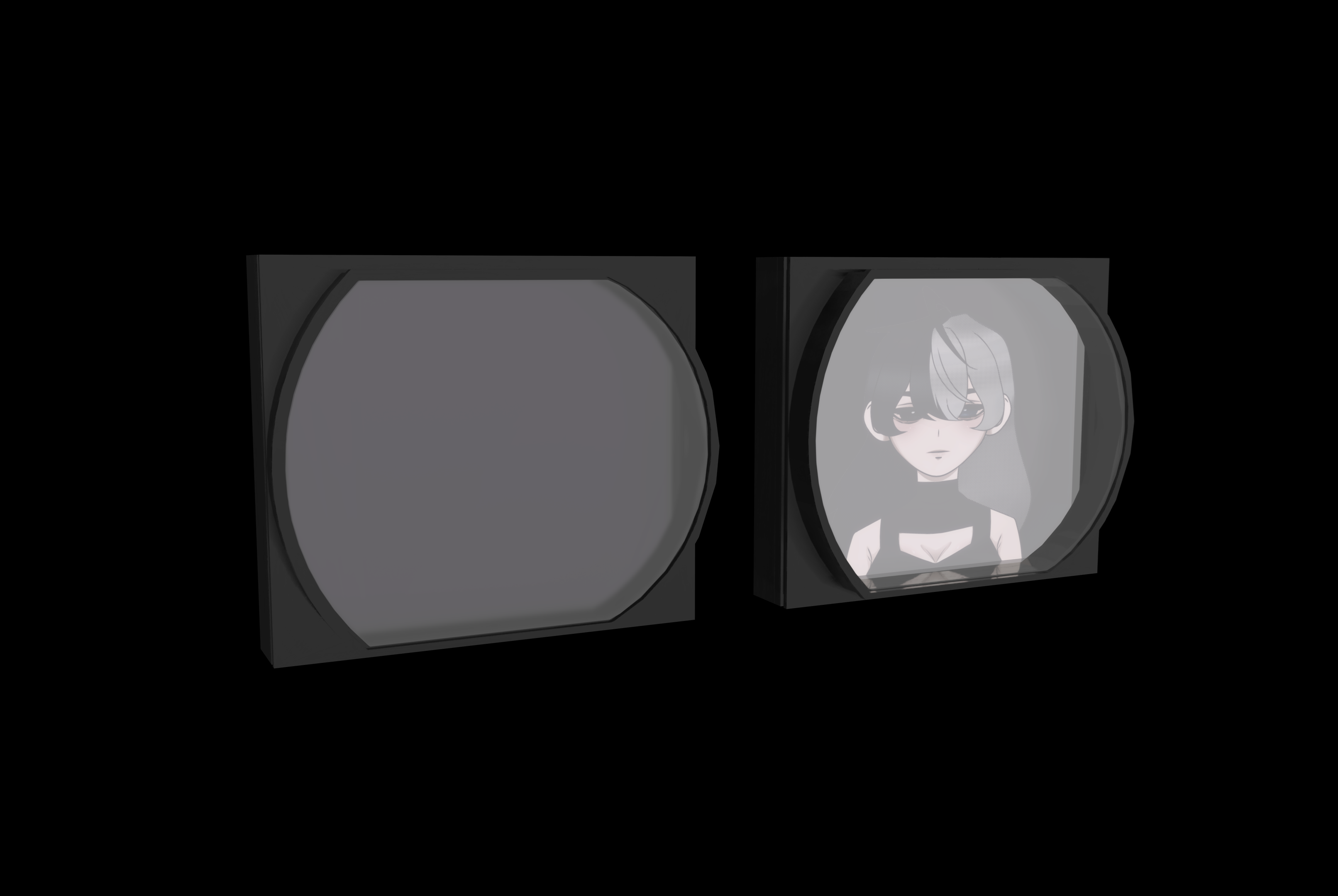
(Left picture is without display, right with; that's Mira BTW, you'll learn more about her in another project soon! Give the artist, Kennaness, kudos here! Showing artists love lets them know that they're appreciated!)
Pretty nice!

And here's an opened up view; from left to right we are looking at the
- Backmost piece (Holds display )
- Polarizer Lens
- Division piece
- Fresnel 1
- Lens holder (Moves back and forth + holds lens)
Now, I’m also thinking of placing a camera in one of the blind spots of the backmost enclosure—most likely at the corner of the display—aimed at the polarizer. This should allow the reflection of the eye to be captured and used for eye tracking.
I also need to determine the optimal distances for the lens, so I’ll be calculating measurements for three different display sizes. Hopefully, I’ll have an update on that soon. Until then?
~Stay Cool
Discussions
Become a Hackaday.io Member
Create an account to leave a comment. Already have an account? Log In.