Using this ULA clone the standard QL video outputs will work as before but to see the new colors a new mixer is needed and so new video connector is needed for the 16 colors mode. For that the most practical solution is to use the RF RCA connector by de-soldering the rf wire and soldering the new composite video signal in it's place.
JP2 is the composite video output and use a shielded wire to connect it to a RCA (could be the QL's rf output one) or BNC connector. The trimmer capacitor must be adjusted to obtain the best picture quality.
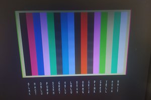
To enter the 16color mode: poke 98401,1
To load the commands use the tk2 command: lrespr colsubs
The first command is PLOT x,y,col sets the point at x,y to color col. x,y take values 0..255, left down corner is 0,0 and col = 0..15
The second is COLSUBS x1,y1,x2,y2,col that replaces pixels with color col in the defined rectangle with the lighter version of the color
x1,y1,x2,y2 take values 0..255, left down corner is 0,0 and col = 0..7
x1,y1 is the left down corner and x2,y2 the right up corner
To choose a different palette for mode 4 use: poke 98401,n where n=0 or 2,4,6,8,10,12,14 (0=the standard)
To choose the brighter output on standard video mode: poke 98401,128 or with the other palettes of mode 4 poke 98401,128+n where n=2 or 4,6,8,10,12,14
Hardware design and software released under the Creative Commons License BY-NC-SA
BOM
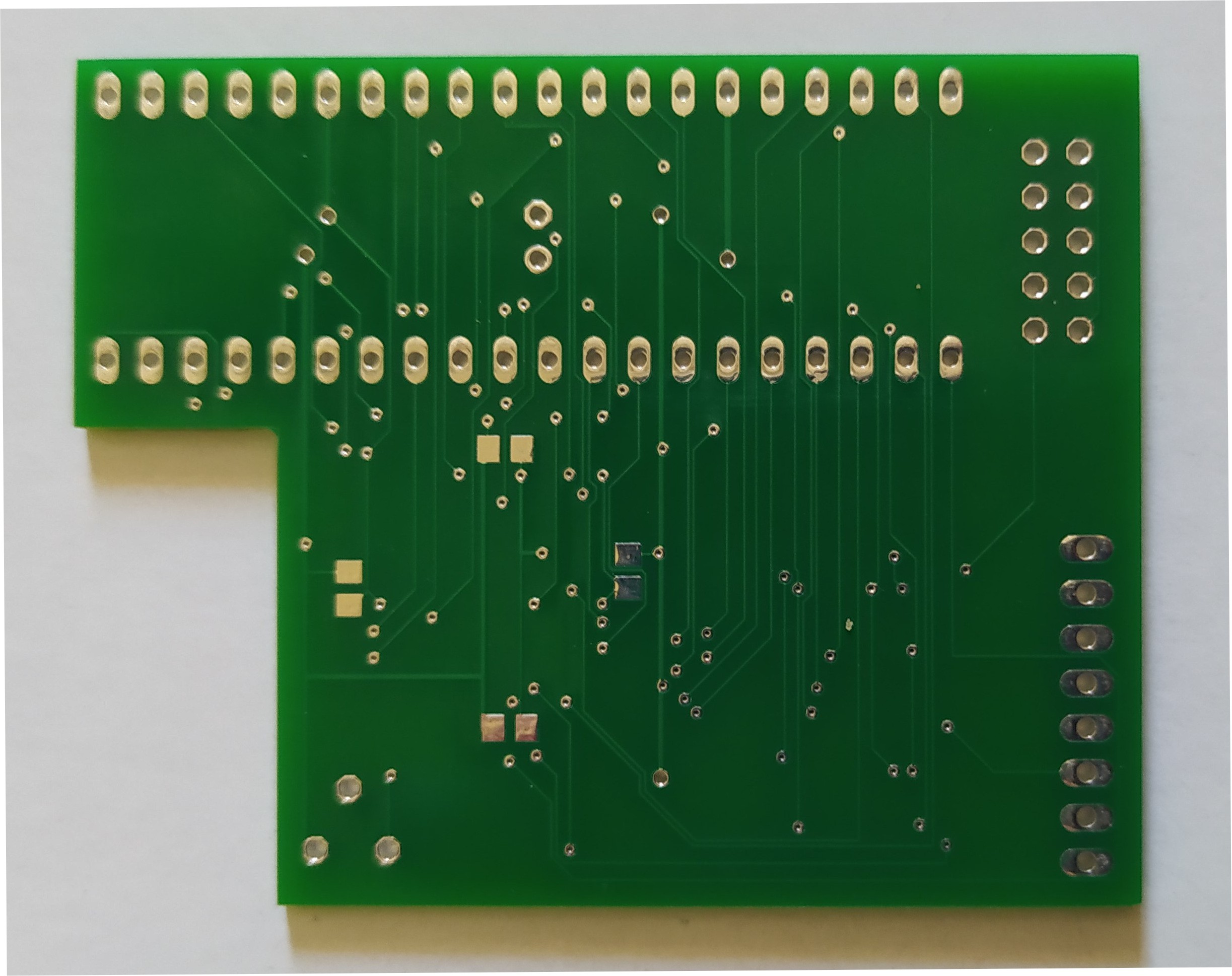
EPM7160STC100 altera cpld
AD724 pal encoder
74LS241 or 74LS244 ttl buffer the smd package.
11 x 100nf smd 0805 capacitors.
1 x 220uf electrolytic (thin for pins to bend and positioned horizontally at C13)
2 x 4,7uf multilayer ceramic. (connect in parrallel to C2)
1 x 5-50pf trimmer capacitor C12
one 30Mhz 5V active crystal oscillator smd
one 4,43 Mhz crystal Q1
R1,R2,R3 680 Ohm 0805
R4,R5,R6 1.2K 0805
R7,R8,R9,R11 100 Ohm 0805
R10 470 Ohm
R12 560 Ohm
R13 330 Ohm
R14 4.7K
R15 75 Ohm
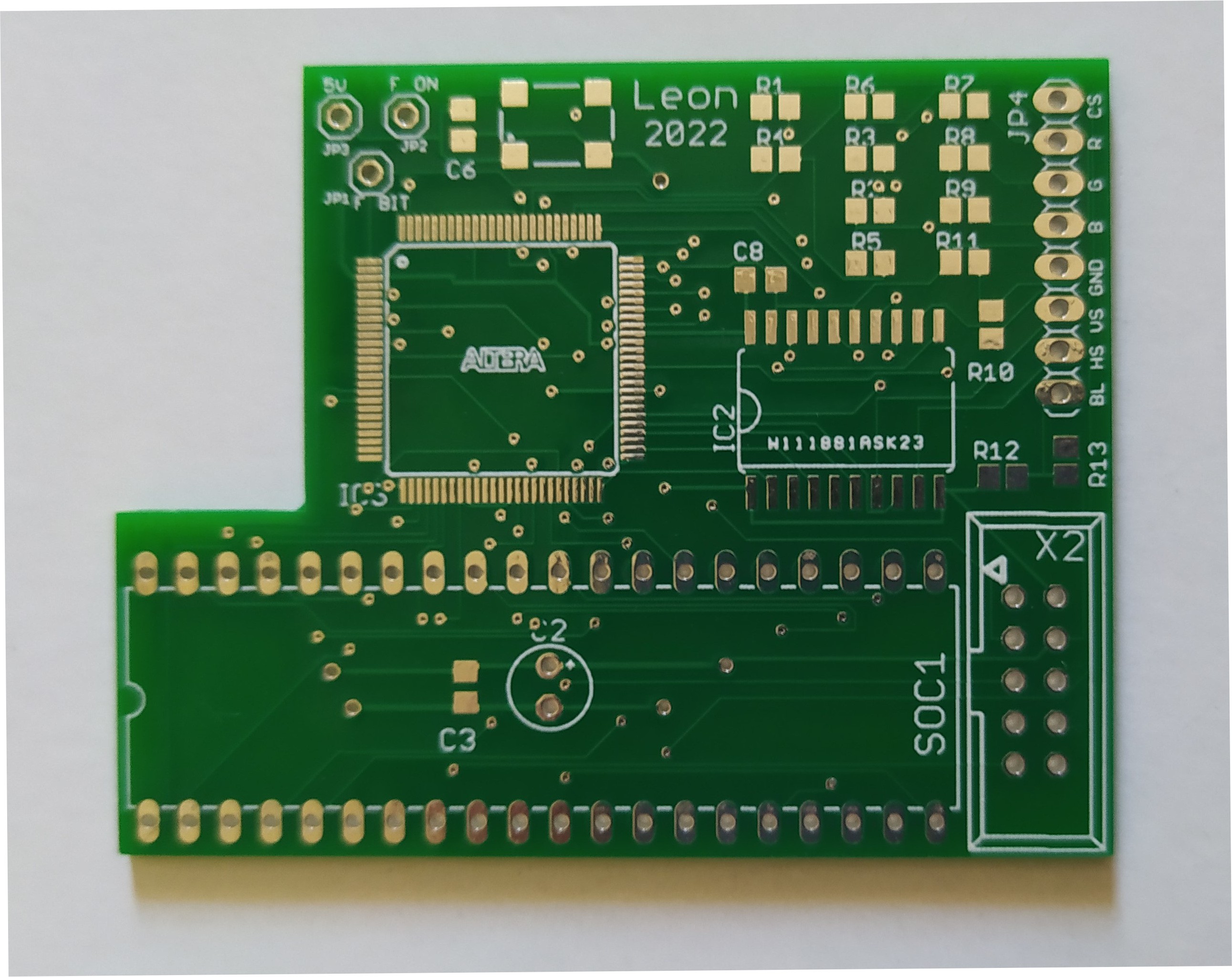
2x5pins header for the programming port (that I don't solder on the pcb, I just lightly and partially sideways press in the holes as long as the programming lasts).
And 40 thin pins (2x20 header) to solder on the pcb that will fit in the original ULA socket, these pins should be thin enough not to damage the socket.
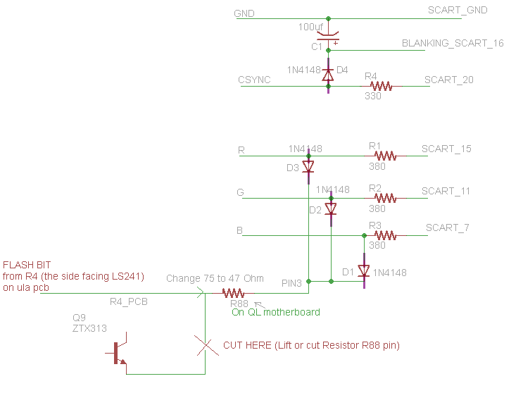
To take out the flash signal to the video connector of QL and be able to make a scart cable is possible if you use pin 3 of the connector. This is a monochrome composite video that maybe no one uses. So by lifting (or cutting) one pin of resistor R88 and connecting a 47 Ohm resistor to the other pin you can implement the scart cable that will be able to produce the 16 colors.
The the following image shows how the scart cable should be made:
 Leon
Leon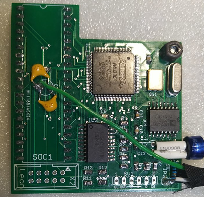


 Dan
Dan
 Lutetium
 f4hdk
f4hdk
Hi. Is it possible to pass the signal through a programmable pallet, such that you get 16 or 4 colours out of 256 or more?
Is it possible to have 256 mode 256 colours and 512 16 or 256 colours? Does the chip have internal memory for this? Would be nice to have.
Is it possible to have any software compatible modes with Q68 and other motherboards or the FPGA board with sprites? Like a bit more higher resolution?