Close
0%
0%

ZX8301 replacement for Sinclair QL

Having burned two ZX8301 chips in the last years was a motive to make a cpld based replacement for the QL ZX8301 ULA.

Similar projects worth following
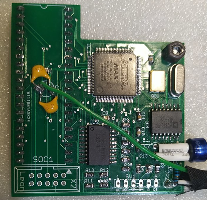
After reading Nasta's description of the ZX8301 ULA I programmed an Altera EPM7160S cpld in VHDL and made a pcb that replaces it.

The ULA replacement has the following features:

- Buffering of the standard QL video signals.
- 16 colors option for video mode 8 available through RGBS or a NEW composite video output
- AD724 pal encoder for better composite video quality
- 8 palettes to choose from, for the 4 colors of mode 4 and for the 16 colors
- Software switching of modes

16 colors mode is not supported by the existing software so I wrote in assembly 2 Basic extension commands to plot in 16 colors and replace colors with the new ones.

Build at your own risk.

*** As it turned out it doesn't work with Gold Card (GC/SGC). See my other projects here for a compatible version ***

Copyright (c) 2023 T. Liontakis

Hardware design and Software released under the Creative Commons License BY-NC-SA

Using this ULA clone the standard QL video outputs will work as before but to see the new colors a new mixer is needed and so new video connector is needed for the 16 colors mode. For that the most practical solution is to use the RF RCA connector by de-soldering the rf wire and soldering the new composite video signal in it's place.

JP2 is the composite video output and use a shielded wire to connect it to a RCA (could be the QL's rf output one) or BNC connector.  The trimmer capacitor must be adjusted to obtain the best picture quality.

To enter the 16color mode: poke 98401,1

To load the commands use the tk2 command:  lrespr colsubs

The first command is PLOT x,y,col sets the point at x,y to color col. x,y take values 0..255, left down corner is 0,0 and col = 0..15

The second is COLSUBS x1,y1,x2,y2,col that replaces pixels with color col in the defined rectangle with the lighter version of the color

x1,y1,x2,y2 take values 0..255, left down corner is 0,0 and col = 0..7  

x1,y1 is the left down corner and x2,y2 the right up corner

To choose a different palette for mode 4 use:   poke 98401,n where n=0 or 2,4,6,8,10,12,14 (0=the standard)

To choose the brighter output on standard video mode: poke 98401,128 or with the other palettes of mode 4 poke 98401,128+n where n=2 or 4,6,8,10,12,14

Hardware design and software released under the Creative Commons License BY-NC-SA


BOM

EPM7160STC100 altera cpld

AD724 pal encoder

74LS241 or 74LS244 ttl buffer the smd package.

11 x 100nf smd 0805 capacitors.

1 x 220uf electrolytic (thin for pins to bend and positioned horizontally at C13)

2 x 4,7uf multilayer ceramic. (connect in parrallel to C2)

1 x 5-50pf trimmer capacitor C12

one 30Mhz 5V active crystal oscillator smd

one 4,43 Mhz crystal Q1

R1,R2,R3 680 Ohm 0805

R4,R5,R6 1.2K 0805

R7,R8,R9,R11 100 Ohm 0805

R10 470 Ohm

R12 560 Ohm

R13 330 Ohm

R14 4.7K

R15 75 Ohm

2x5pins header for the programming port (that I don't solder on the pcb, I just lightly and partially sideways press in the holes as long as the programming lasts).

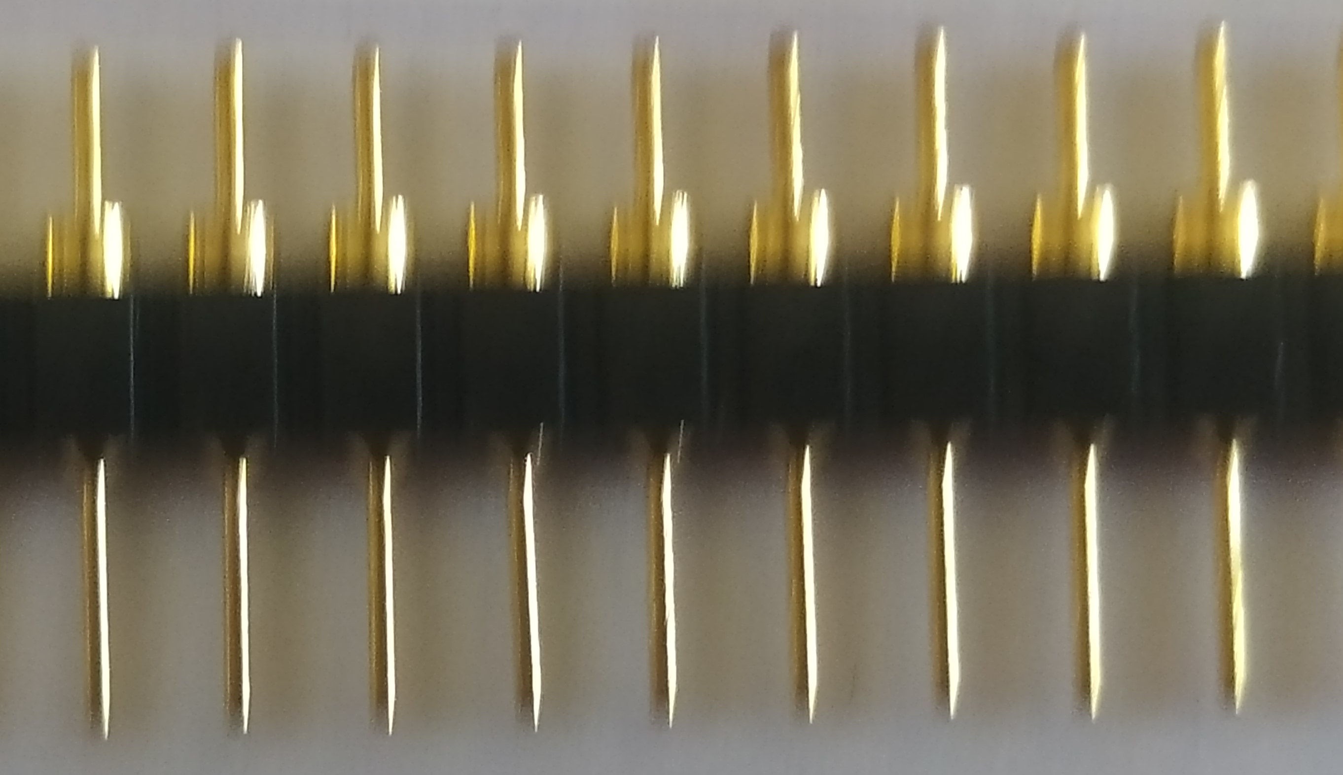
And 40 thin pins (2x20 header) to solder on the pcb that will fit in the original ULA socket, these pins should be thin enough not to damage the socket.
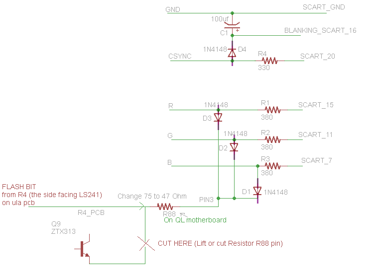
To take out the flash signal to the video connector of QL and be able to make a scart cable is possible if you use pin 3 of the connector. This is a monochrome composite video that maybe no one uses. So by lifting (or cutting) one pin of resistor R88 and connecting a 47 Ohm resistor to the other pin you can implement the scart cable that will be able to produce the 16 colors.

The the following image shows how the scart cable should be made:
ZX8301.pof

Firmware, 9/4/24 shifted the display 2 lines up

pof - 9.82 kB - 04/10/2024 at 06:20

Download

older_ula.zip

Files of the older more compact ula board without the AD724 IC

x-zip-compressed - 735.37 kB - 04/18/2023 at 15:08

Download

COLSUBS_bin

plot and colsubs commands

colsubs_bin - 434.00 bytes - 01/24/2023 at 15:54

Download

sch_pal.png

Schematic

Portable Network Graphics (PNG) - 37.73 kB - 01/24/2023 at 15:33

Preview

zx8301_smd160_pal.zip

PCB production files

x-zip-compressed - 20.95 kB - 01/24/2023 at 15:22

Download

  • PCB with PAL encoder AD724

    Leon03/31/2023 at 12:25 0 comments

    PCB with PAL encoder AD724

  • New pcb using the EPM7128STC100 smd IC

    Leon11/22/2022 at 12:53 0 comments

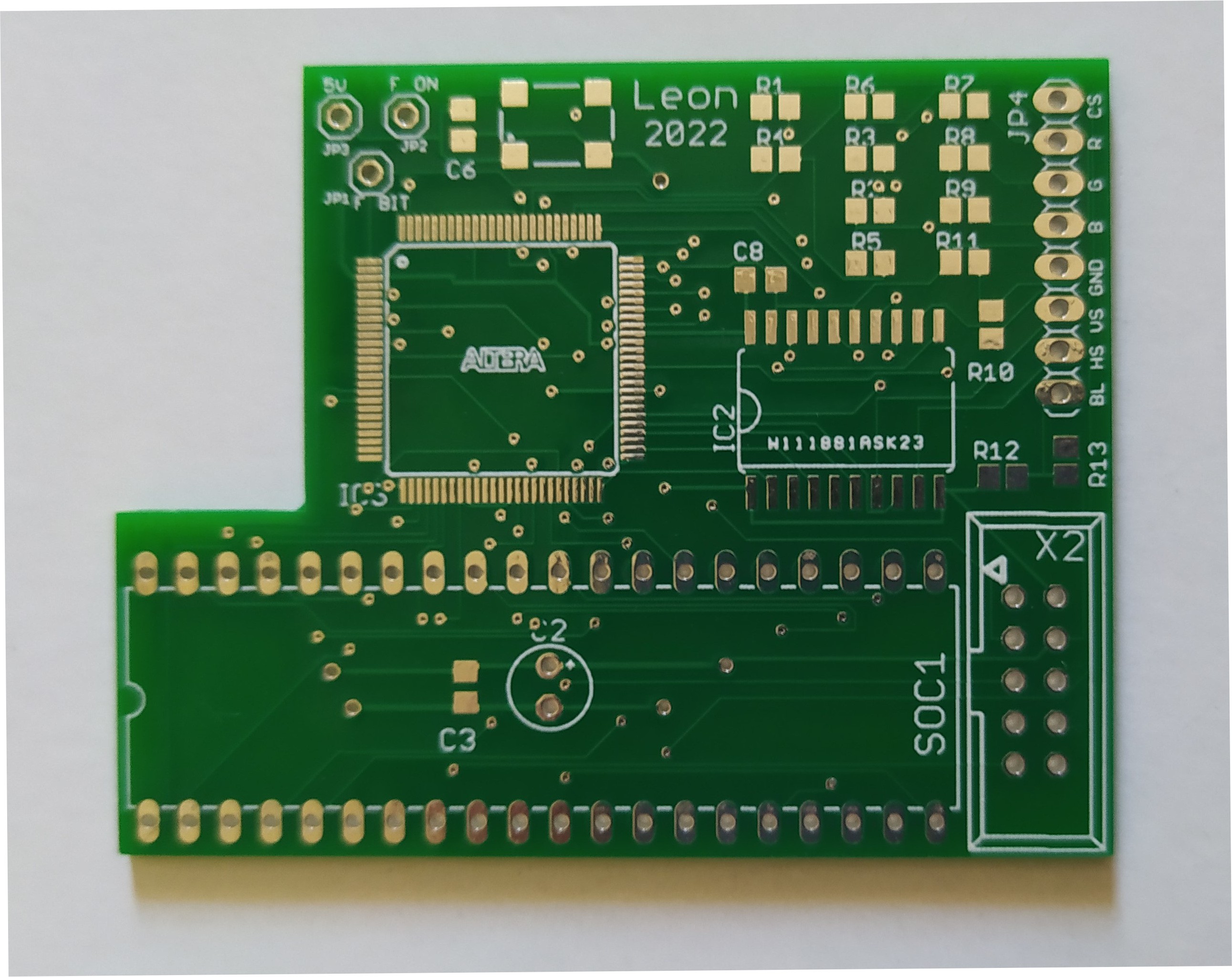
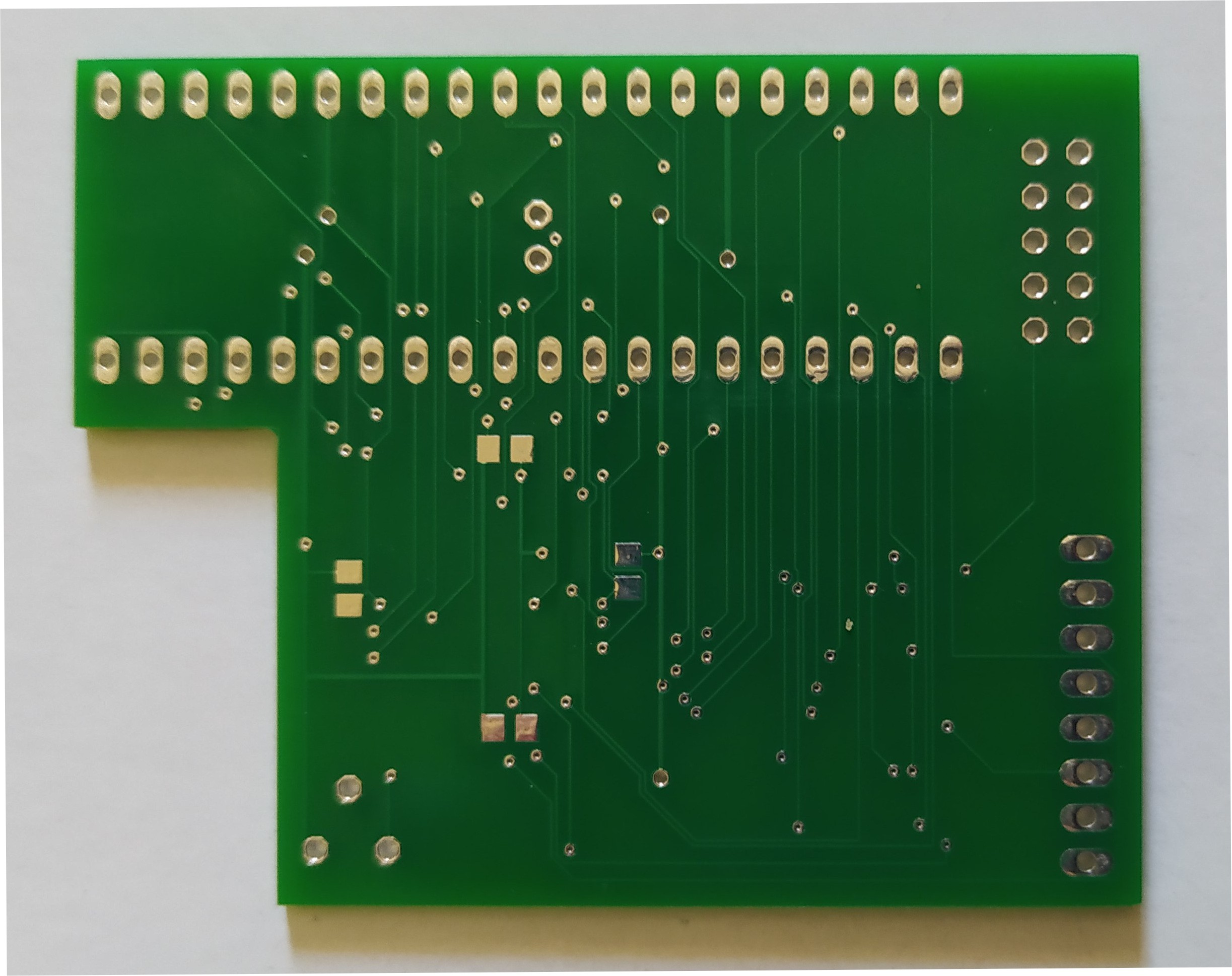
    Received the new PCBs for the EPM7128STC100 smd version from PCBWay.

    I use PCBWay for my project's pcb production and I am very satisfied with the results, I always get perfect pcbs with very fast production and delivery times and low cost. See this article for more info about the PCBWay service quality.

    I am waiting for the EPM7128STC100 ic I ordered and soon I'll test the new design that provides extra RGBs outputs with mixing of the flash bit for 16 colors. After testing I'll publish the new pcb data.

View all 2 project logs

Enjoy this project?

Share

Discussions

Wayneaswell wrote 05/19/2024 at 04:38 point

Hi.  Is it possible to pass the signal through a programmable pallet, such that you get 16 or 4 colours out of 256 or more?

Is it possible to have 256 mode 256 colours and 512 16 or 256 colours?  Does the chip have internal memory for this?  Would be nice to have.

Is it possible to have any software compatible modes with Q68 and other motherboards or the FPGA board with sprites?  Like a bit more higher resolution?

  Are you sure? yes | no

Leon wrote 05/19/2024 at 07:19 point

Yes but it is another project, see this https://youtu.be/PXaGN5iNngw

  Are you sure? yes | no

Wayneaswell wrote 05/20/2024 at 09:19 point

Thanks

So this plugs into the zx-8301/68008 socket?  Sounds great.  Where is the project page for this?  Where do we get one?

  Are you sure? yes | no

Wayneaswell wrote 05/20/2024 at 10:24 point

My apologies, I got that wrong.  I-fuse is not used in CPLD.

  Are you sure? yes | no

kevin_2016 wrote 04/04/2024 at 16:10 point

Hi Leon,  firstly, thanks you all you work on this - it is truly great and much needed for the QL. I have built two of your original older ula replacement boards without the AD724 IC and they are working great. I have however noticed that the bottom of the picture seems to be cut off. I'd say the lower two pixel rows are missing:

https://drive.google.com/file/d/168ubst6TxRk6w9RkNCAxgrn_xc21Yv0a/view?usp=sharing

I am using a QL-to-VGA with a Pi Pico and do not see this problem with an original ZX8301.

Is this a CPLD firmware thing that you are able to fix?

Thanks again

Kevin.

  Are you sure? yes | no

Leon wrote 04/04/2024 at 20:46 point

Yes I think I can, send me your email in a pm

  Are you sure? yes | no

Similar Projects

Does this project spark your interest?

Become a member to follow this project and never miss any updates