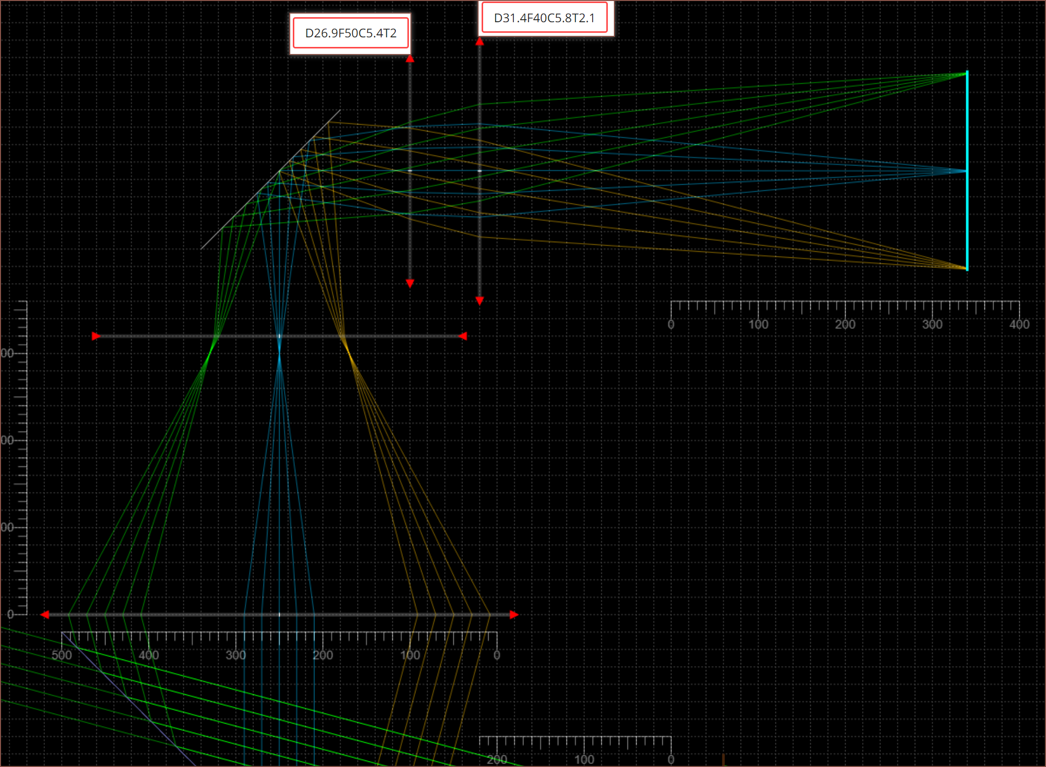
 I've hopefully got a new solution for the optical pathway, and I should have a better understanding of how things should work out.
- For an 18.4mm active area and intending to use 4:3 virtual monitors, the visible diameter is 23mm.
- The 55mm fresnel lens is F-30, though this and everything else likely would change because I haven't taken the users head into consideration and the rays might be intersecting it.
- The lens straight after that is the D42 F-40 I've already got.
- The mirror is likely to be slightly tilted so that the optical elements after that are parallel with the top slope of the helmet, but for now I'm just using a 90 degree bend in this simulation.
- Then there's 2 double convex lenses that obtain the 23mm focus disk.
- Tracing backwards from the screen, it seems that the centre of the eyebox will see a slight dimming of the edges. If the eye is closer to the edge of the eyebox, the centre of the virtual monitor may appear dimmer than the edges. OLED has some good viewing angles though so I don't think this should be a critical issue.
- The entire optical path + screen would likely fit under 40mm from the front of the eye, which is probably on or near the ear/scalp circumference of the head.
- With the exception of the aspheric fresnel lens, the rays mainly cross though the inner 50% of the lenses which hopefully will reduce abberations.
- The second lens is exposed (it'll be partially sticking out of the inner helmet "ceiling") and very close to a focal point. This could mean that dirt on the surface of the lens would be visible.
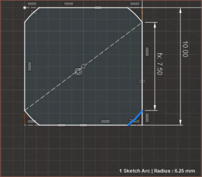
A possible thing that is incorrect is that I'm using the 10mm eyebox. Maybe I'm supposed to use the larger 12.5mm diameter FOV circle (see below) or be using 18.4mm as the screen size in the simulation instead of 23mm. Maybe this just means the actual eyebox is 10mm * 10/12.5 = 8mm, which should still be servicable.

 kelvinA
Discussions
Become a Hackaday.io Member
Create an account to leave a comment. Already have an account? Log In.