 Christoph
Here's a mixed alloy board with a switch in the top right corner, a little BGA, and a u.Fl connector (not visible, but it's there! I promise). Those have high temp solder, the rest is low temp and not even completely done. I'll save that for later so that I can take some appropriate pictures.

Remember that when building a prototype, we don't have to assemble everything in one go. We are allowed to
- build it in functional sections (voltage regulators first, then maybe an MCU or other core part, then less vital peripherals) to make sure everything works before proceeding;
- use different alloys in different places to make use of their respective advantages.
These two points are related via the use of low temp solder. It's awesome in the right place. When I want an easy and relaxing assembly experience, i try to use low temp solder in as many places as possible. That's a hard to write list, so let's flip it around:
Use high temp solder where you have to, and low temp everywhere else.
Where to use high temp solder:
- When you have no other choice. All BGAs I came across had high temp balls, but that's kitchen wisdom. It may be possible to get them with low temp balls, but if you had access to such parts you probably wouldn't sift through hackaday for assembly stories;
- For anything that needs a bit more mechanical strength: connectors, switches, buzzers, probably some more;
- For parts that have to be aligned extremely well with the PCB. High temp solder has a stronger pull and will result in better alignment. A decoupling capacitor will not need this;
- For temperature indicator parts - you might need these to show you when the board has reached reflow temperature.
I usually try to limit the number of high temp reflow cycles for two reasons:
- It's harder to get the board to the required temperature;
- higher temperatures are more stressful for the parts.
So the first two reflow cycles are for a limited set of parts as outlined above; one for each side of the board. A stencil doesn't really help, because only a limited set of pads will get high temp paste. Of course you can design a stencil just for high temp parts though, but it's probably not worth the effort.
BGA tips
- Don't apply paste to BGA pads. You'd only smear it all over the place when you place the chip;
- Brush some tacky flux on the BGA's pads on the PCB;
- Check how well the silk screen is aligned with the copper features. If it's not aligned really well, you can't rely on the BGA's silkscreen outline (if it has any) to guide you!
- Place the BGA with tweezers. With some practice you can feel if it's on the pads or on solder mask;
- Put some weight on top! An inductor slightly smaller than the chip is just right. This will make sure that the balls have thermal and mechanical contact with the PCB, and vapor from the flux can't push the BGA around. Too much flux can do that. Don't worry, the extra weight will not squash the solder joints.
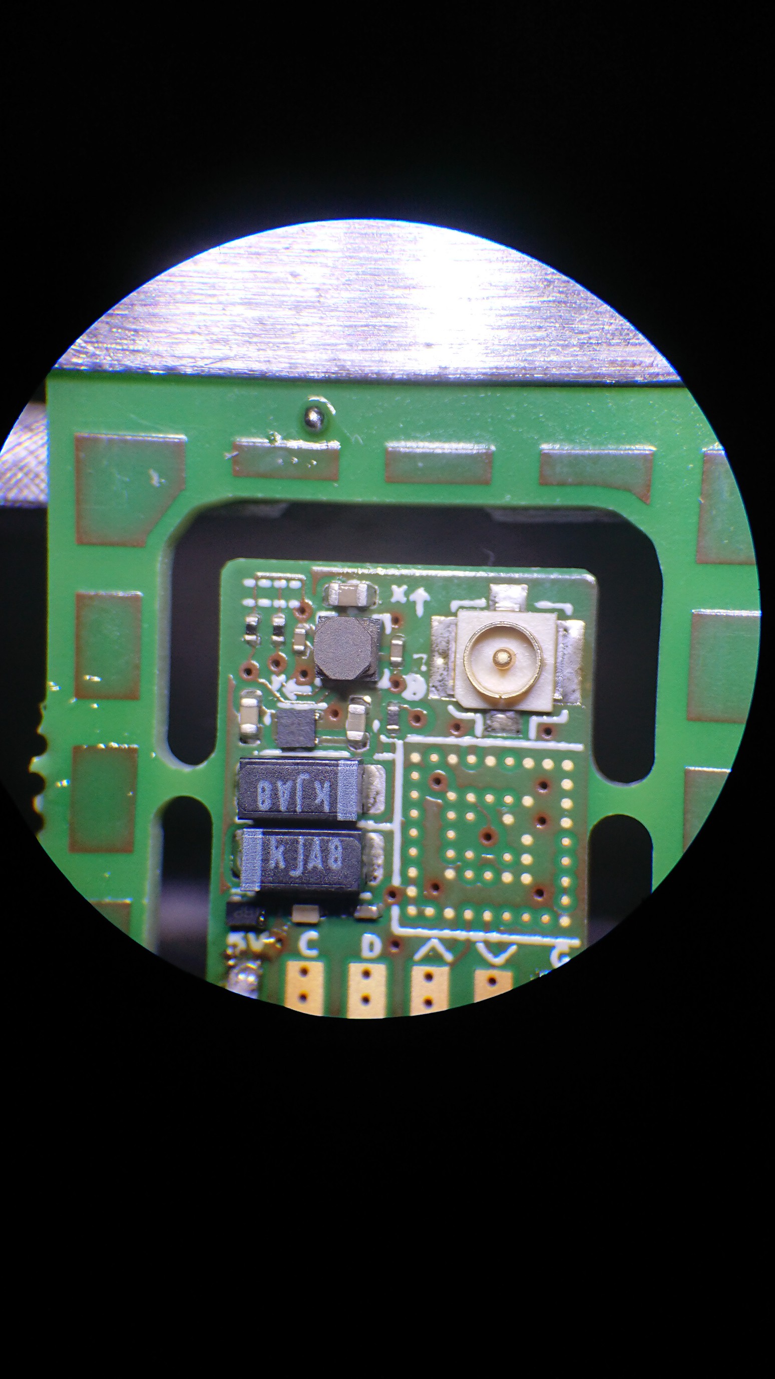
Example for a weighed down BGA (STM32WLE5):
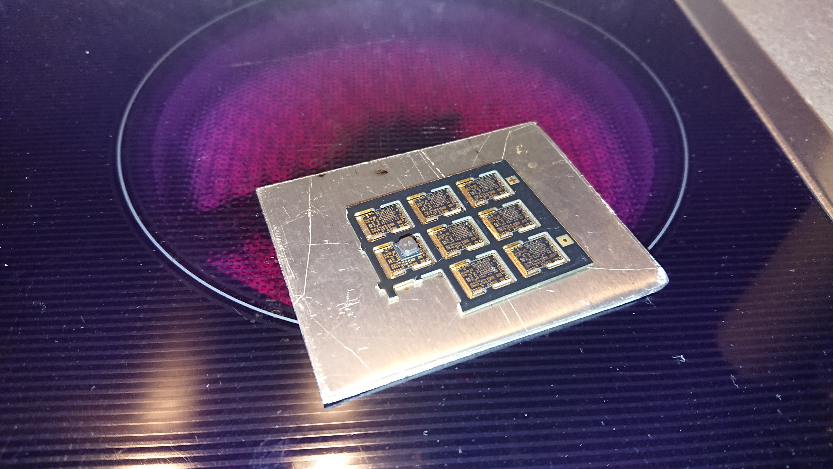
This was one of my earlier boards and I forgot to add some temperature indicator. Like a blob of solder paste (no available space for that) or one or two passives. This is better (a voltage regulator with caps, to the bottom left in the picture at the top of this log):
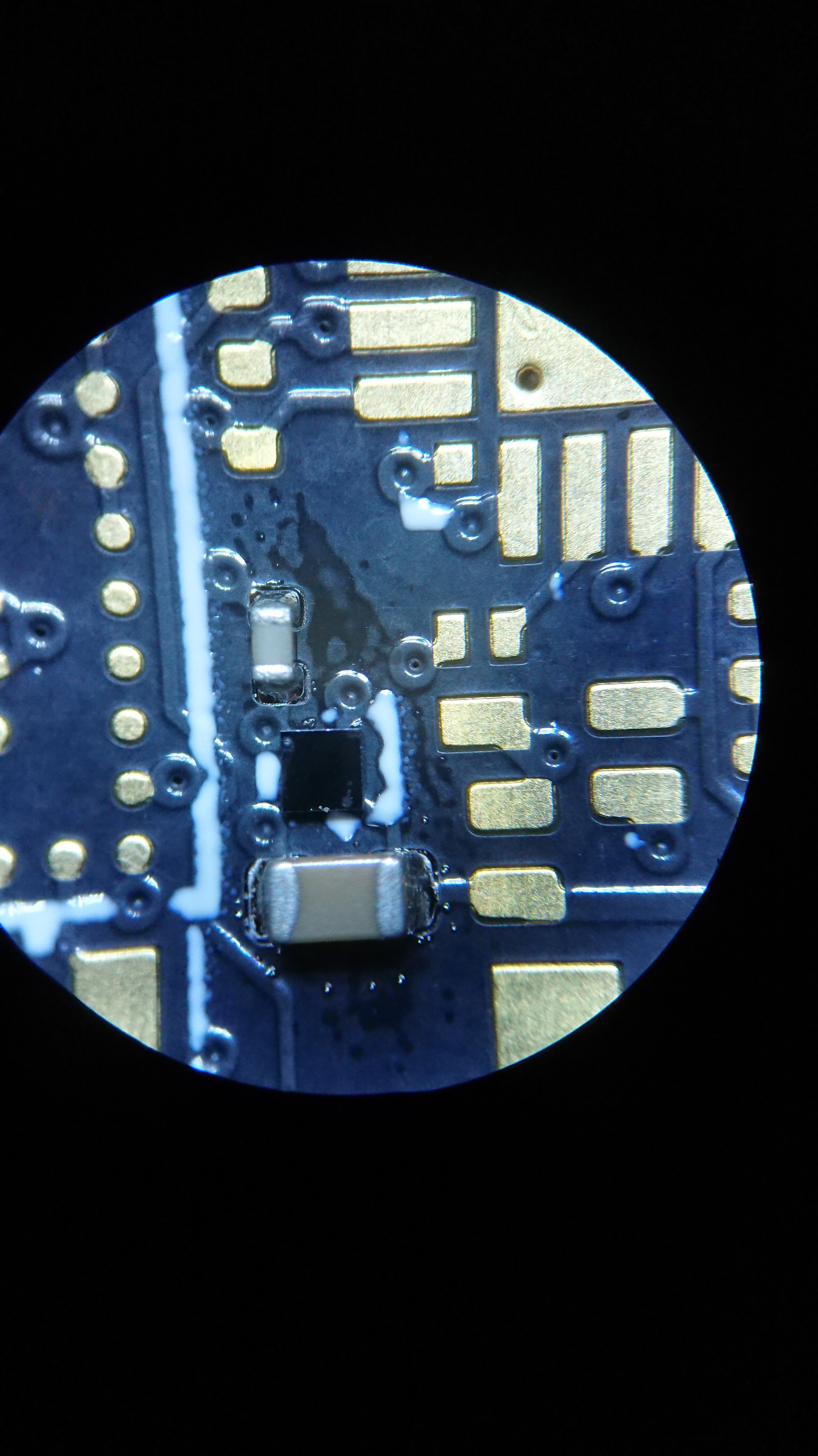
Here I had applied high temp paste for two capacitors (0201 and 0402) right next to the 4-BGA to tell me when the paste reflowed. If the caps are done, the BGA is done, too. I didn't have an extra weight for this one, but it worked nonetheless (again on a hot plate). You can also see that the BGA's silkscreen outline is completely useless.
Spoiler: You can also add extra weight to LGAs:
But more on that later when we get to the low-temp tips. LGAs don't come with the right amount of solder in the right place, so we have to do that ourselves - but at least we get to choose.
Discussions
Become a Hackaday.io Member
Create an account to leave a comment. Already have an account? Log In.