In normal mode the red del makes a small flash per period: 0010000100001000
Pressing the MOD button temporarily switches to recording mode. The green LED is illuminated. I type on the keyboard of the arranger my controls, the system saves ... Once finished, either I press MOD to cancel the recording or on another button to which will be assigned the recording.
A short push on the MOD button allows me to use the record recall buttons as a second database. The red del makes then two brief flashes per period: 00101000010100001010. It is as if I had 18 'Pad'.
Pressing a button (the green LED blinks) recalls the recording assigned to it. If no recording has been assigned a note is sent to the arranger.
I chose to use an Arduino. I start my tests on a deck with ATMEGA1284p to have two serial links. One for MIDI at 31250 bauds and the other for programming and debugging at 9600 baud.
The midi interface is classic but it is really necessary to respect the value of the resistance of 1k out of the Til111. The 63-byte buffer of the serial library is a bit fair. Instead of changing the library I use a programmed buffer that will quickly unload the first.
An important point when you read the MIDI information sent by the arranger: the arranger sends synchronization information on the MIDI bus periodically (about every 30ms). It is necessary to filter them in the software if you do not want to saturate the input buffer ...
When the project was well advanced, I had the idea to insert the diode 1n4148 between the output of the Til and the RX input of the Arduino. This is a find that allows me to switch to Arduino Nano which has only one serial link. Thanks to this diode I can now use the single serial link for programming and MIDI. ATTENTION when programming the Arduino via the IDE it is necessary that the arranger is switched off otherwise it swallows funny commands !!!
The AutoOff circuit is classic. Once the ON button is pressed, the Arduino starts. An output (12) goes high and saturates the 2n2222 which closes the 2n2905. It is therefore necessary to press ON until the output 12 is in the high state.
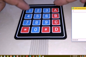
The metal pad buttons have been chosen for their low cost! The management of these 'Pad' is a bit tricky when the power supply to the Arduino is not grounded. But I was able to solve the problems encountered via suitable algorithms. In particular, during the startup phase of the Arduino (SETUP), the 10 'Pad' are self-calibrated. So do not keep fingers on the 'Pad' during start-up.
The principle of managing these 'Pad' is quite simple. When testing a 'Pad', the spindle is connected to which it is connected in the high state for 10ms. Then, the spindle is switched to a high impedance input and the time it takes to fall to the low state is measured by the resistance of 1MW which connects it to zero. This duration of a few micro seconds increases when your finger touches the pad and even if the pad is varnished as in my case. It is a capacitive effect.
During the realization I realized that the box was a little small. So I decided to use only one 5-pin DIN. So I cut a MIDI cable in half and made a connection to connect the MIDI IN and MIDI OUT jacks to a single 5 pin DIN plug. My choice of connectivity allows, once the box programmed with the arranger to use a single standard MIDI plug. I am satisfied with this choice which only makes my case one take.
During the debugging phase on the Arduino Nano, I used an I2C 64x128 display. It allowed me to display a certain amount of information that I left in the program. A test at start-up verifies the presence of this optional display.
I also used combinations of keys (2 'Pad' pressed at the same time) to add features:
• 2 & 8 => Free RAM display (if display) and returns to MIDI mode
• 3 & 9 => Switches to 9600 Baud serial mode and displays programs recorded on PC
• 3 & 7 => Defragmentation of the EEPROM and (if display) displays the free... Read more »

 Greg Kennedy
 Stefano Garuti

 Maciej Witkowiak