 GOAT INDUSTRIES
 Using one of my universal prototyping boards, I rigged up some gates along with the timer chip in the hope of being able to get the full range of time intervals that should be available from the timer. So far the max has been 30 minutes before the circuit started to fail. 2 hours is the ultimate goal.
The plan is to use the basic pulse output that the timer chip seems to be able to output without too much trouble, rather than try and get the chip to 'hold' in the HIGH state before a 'release' signal is sent from the MCU. After a bit of head scratching I worked out that I could use CMOS gates to create my own hold function. I imagine that this is technically some kind of latch, I dont really know!
I firstly envisaged using an AND and an OR gate together with a feedback loop from the OR back to one of the AND inputs to create a HOLD. After looking more closely at the logic tables I realised that I needed to extend this to an XOR gate which ensures that if there are no signals whatsoever on both the inputs then the output is LOW. The theory looked good and I added a load of pull down resistors to all the inputs to stop random static from inadvertently triggering the gates.
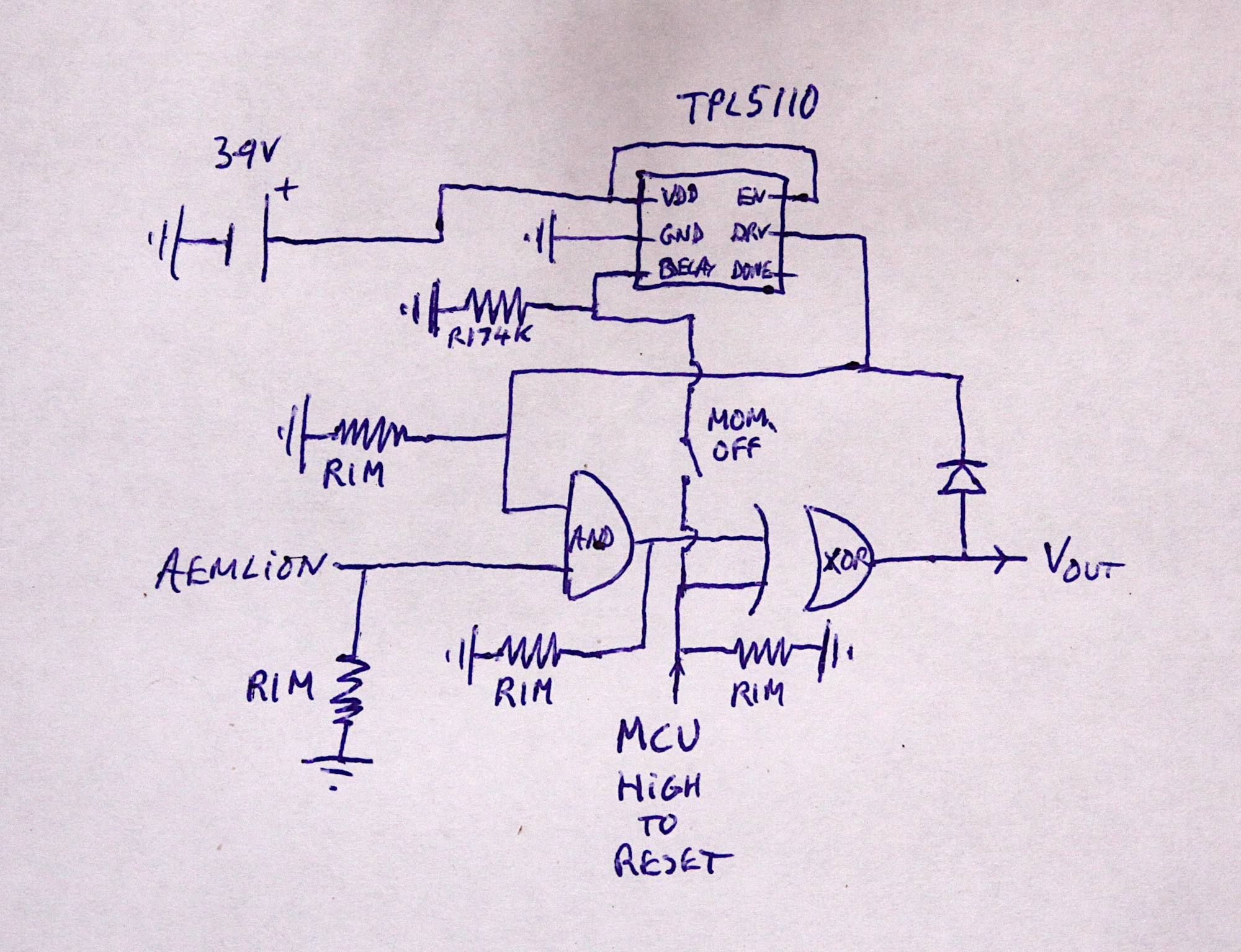
Keen observers will note the use of a diode in the feed back loop and a momentary OFF switch to isolate the DELAY pin in the timer. when doing the initial programming. Without the diode, the circuit behaved with slightly wrong logic and I have almost no idea why! Without the momentary switch, the DELAY pin in the timer sensed resistance through the MCU and the time interval became badly affected.
So far, as tests continue, the circuit seems to be working even with all the wild array of wires flying about all over the place creating gallons of associated parasitic capacitance. Maybe this circuit is now immune to parasitics?
Discussions
Become a Hackaday.io Member
Create an account to leave a comment. Already have an account? Log In.