 Colin M
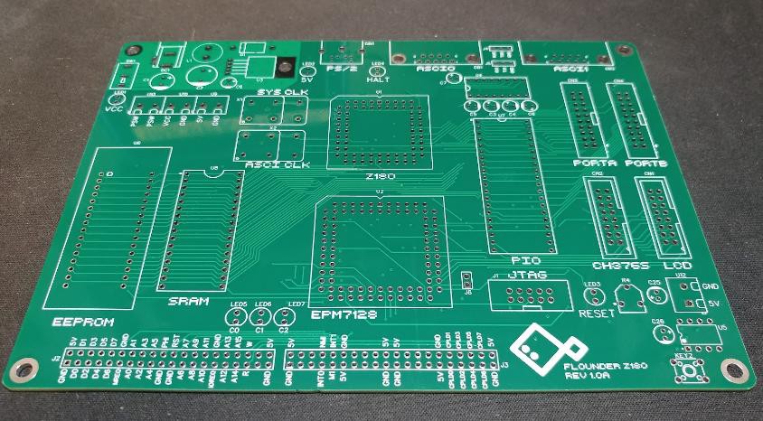
The PCBs are here!
 There are no obvious manufacturing issues or design problems that I can see, so it's time to start building. First step is the regulator circuit. It's a simple LM2576 buck converter stepping the 12v input down to 5v.
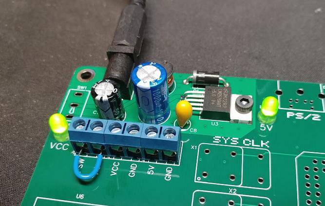 Nothing blew up and the LEDs come on. Multi-meter shows a solid 5v on the output. Good start.
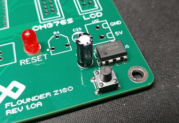
Next up is the 555 power-on reset. I've used this exact circuit in other projects, so I didn't expect too many issues. After soldering (the resistors are SMD parts on the back of the board), a quick test shows it's working as expected.
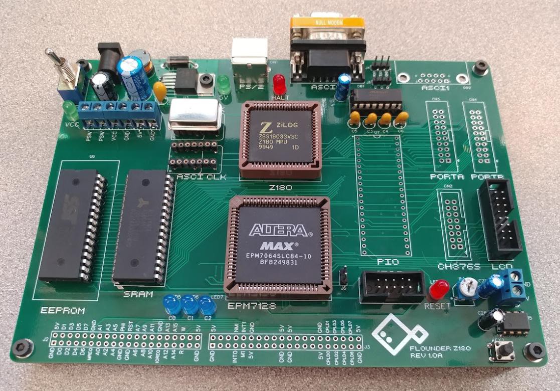
 In the first Flounder prototype, I used the 44-pin version of the EPM7064 CPLD, but on this PCB, I opted for the 84-pin package. I was a little nervous I missed something obvious in the transition, but happily, that was not the the case. The CPLD has two clock inputs: the PHI output from the Z180 and a second oscillator directly connected. Since the Z180 is not yet installed, I soldered in the secondary oscillator and the CPLD along with its debug LEDs and programming header.
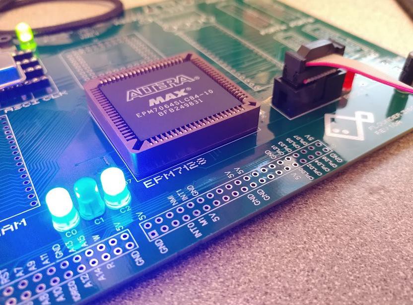 Quartus detected the CPLD right away and I was able to program a simple counter/blinker circuit to test the clock input and LEDs. The CPLD is alive!
It's a bit hard to test the Z180 without the ROM and RAM also hooked up, but to reduce the number of variables, I connected just the CPU at first. I updated the CPLD program to output all zeros on the data bus and I powered on the system. On the oscilloscope, I could see that PHI was at half the frequency of the clock oscillator and there was a lot of activity on the address bus. The Z180 is happily executing NOPs. Not much else to do now but hook up the memory and a serial port and see what happens.
After some inevitable difficulties updating the decoder Verilog for the larger CPLD, I installed the ROM and RAM and connected a serial port.
 The serial monitor is running! Very nice. With the CPU, memory, and serial port working, everything else feels like a bonus.
I connected the MAX3232 and the DB-9 plug to test that the monitor still runs over RS-232. All good. Finally, I added the PS/2 connector and verified I'm still able to decode key presses.
Still left to go: the PIO and the port A/B connectors, the LCD display, and the CH376S USB adapter.
It's great to have the core functions of the system working. I've got one more week in the Retro Challenge to finish validating this board. I'd like to cleanup some of the software in that time as well.
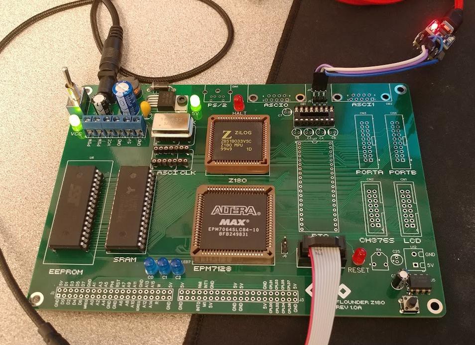
The board as it stands now:
Discussions
Become a Hackaday.io Member
Create an account to leave a comment. Already have an account? Log In.