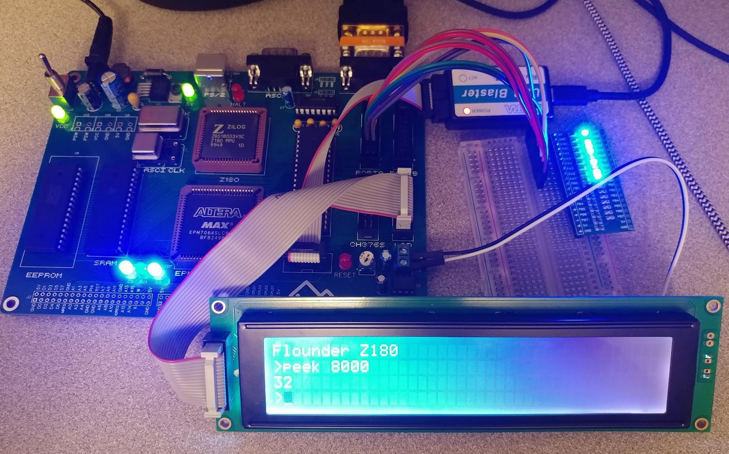
The bad news first: there are a few flaws in the PCB design. Fortunately none of them are showstoppers. The first problem is the footprint for the ZIF socket has holes that are too small to actually fit the ZIF socket legs - just a dumb oversight, but it means I'm stuck using a regular DIP socket for now.
The second issue is less of a design flaw and more user error, but the box header I put in place for the LCD display is mirrored from the connector on the LCD. In reality, I think it's actually correct and I had the connector on the wrong side of the LCD, but either way, I overlooked this when testing and may have fried something on the first Flounder PCB when I hooked it up.
Surprisingly, after reversing the connector on the LCD and building up another Flounder PCB, the LCD still worked as expected. This did cause me to spend a lot of time debugging random stability problems on the first PCB until I gave up and built another. I'm still not sure if the LCD connection is to blame for the first board's problems. I'll have to revisit it.

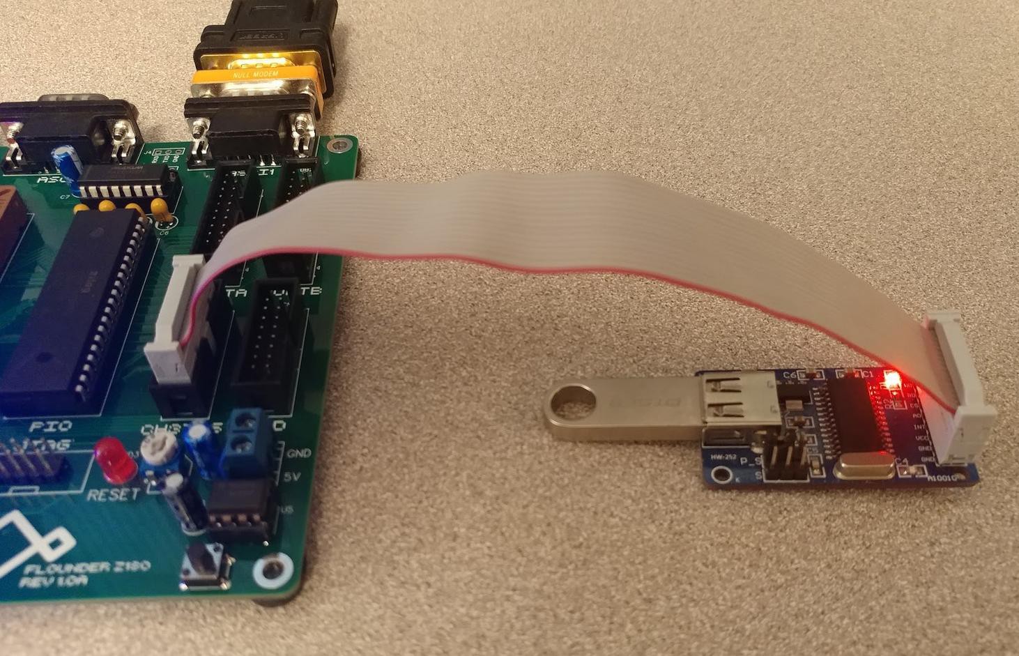
For now, though, I have a fully working Flounder PCB. I reran all of the tests from my last post on the new board and continued testing the remaining peripherals. We know the LCD is working. The PIO ports also work correctly. The final check was to prove I had a connection to the CH376S adapter. I still have no code written to support it, but I was able to verify its connection with I/O peeks and pokes.
 Overall, I couldn't be happier with the first revision of this PCB. There are a few minor tweaks to make for the next iteration, but there's no rush on that. I have feature parity with my prototype and nothing is blocking me from spending some time on the software side to get Flounder doing something fun. I've only got a few more days in the Retro Challenge and I'd like to have a cool demo to show off instead of just a serial monitor program.
 Colin Maykish
Discussions
Become a Hackaday.io Member
Create an account to leave a comment. Already have an account? Log In.